Torpedo fire control system and Lut torpedoes
English version is unfortunately not available.
Try translation by Google Translate.

")
English version is unfortunately not available.
Try translation by Google Translate.
On 22 August 1941, BdU (Befehlshaber der U-Boote, U-Boat High Command) directed a query to TVA (Torpedoversuchsanstalt, Torpedo Experimental Station), if G7a (T I) wet-heater torpedo could be modified in such way that after travelling the pre-set distance, it would start to circle with diameter of 1000 – 1500 meters. This query resulted from the idea that in the case when torpedo missed the target in convoy, the remaining torpedo run could be utilized to circle (inside the convoy), thus creating the another chance for hit. For instance, the G7a wet-heater torpedo with the maximum running distance of 12500 meters (at 30 knots), launched to the target 1000 meters away, after missing, run for another 10 km. If it started to circle (after missing the target) with diameter of 1000 – 1500 meters, it would make 3 – 2 rounds before exhausting the fuel, crossing the courses of the other ships in convoy.

Drawing 1. The BdU idea of the circling torpedo
The drawing presents the track of the torpedo that after travelling distance of 1000 meters starts to circle with diameter of 1200 meters. The blue dashes represents the ships in convoy (length of the ship 130 meters, distance between ships in the column 500 meters, distance between columns 1000 meters).
The initial assessment stated that such modification was feasible, so on 25 November 1941 it was decided to start development of such control device for T I wet-heater and T II electric torpedoes. The control device was temporarily designated as "K-Einrichtung" (Kurvensteuerung-Einrichtung).
The theoretical researches proved that only small fragments of the track of the torpedo circling with so large diameter provide the correct impact angle, assuring the proper operation of the impact pistol (i.e. in range of 30 – 150°) and that the convoy quickly leaves the danger zone created by circling torpedo. Moreover, the rudder deflection required to make turn of so large diameter (above 500 meters) was only 0.7-3.5° (depending on torpedo speed). The torpedo track deviated from the circle because it was impossible to precisely control so small rudder deflection.

Drawing 2. Impact angles of the torpedo circling with diameter of 1200 meters
Therefore, aside from the circular run (Kreisläufer) proposed by BdU, TVA considered the loop run (Schleifenläufer), spiral run (Spiralenläufer) and zigzag/saw run (Sägenläufer).
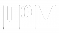
Drawing 3. Loop (Schleifenläufer), sipral (Spiralenläufer) and zigzag (Sägenläufer) torpedo run
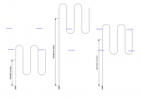
Finally, the loop run was selected for further development. The torpedo track had a shape of lengthen loops which moved along the convoy course, so longer fragments of the torpedo tracks provided required impact angle.

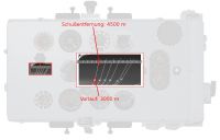
Drawing 4. Loop running torpedo and the convoy
The blue dashes represents the ships in convoy (length of the ship 130 meters, distance between ships in the column 500 meters, distance between columns 1000 meters).
The spiral run was rejected due to constructional difficulties and small chances for success. The zigzag run was designated for future development (later implemented as Lut torpedoes)
On the beginning of December 1941 the following requirements of the loop run were defined: two selectable lengths of the loop (kurz and lang, 1190 meters and 1840 meters for G7a torpedoes and 1050 meters and 1750 meters for G7e torpedoes), pre-set length of the preliminary straight run and turn radius equal to 170 – 250 meters (required rudder deflection was 6 - 7°).
According to the schedule, 12 G7a wet-heaters torpedoes were to be converted to the experimental pattern-running models in January 1942, while in April and June 1942, hundreds of pattern-running G7a and G7e torpedoes were to be combat ready.
The development and testing of the control device was conducted by TVA department in Gotenhafen-Oxhöft (Gdynia-Oksywie). This department, based on experience gained while developing electrically controlled gyro GA VIIIs “Specht” for homing torpedoes, developed pneumo-mechanical control gear. The torpedoes fitted with this gear were designated as Fat (Federapparattorpedo, often mistakenly expanded as Flächen-Absuch-Torpedo) and were marked with green strips painted on the torpedo rudder.
The development was delayed so refined version of the pattern-running G7a wet-heater torpedo was ready only on the beginning of October.
The final version of the control gear allowed for:
- selection of the direction of the pattern (relatively to their initial course) – left or right (links, rechts)
- selection of the loop length: long or short (lang, kurz, of length ~1900 meters and ~1200 meters)
- setting the length of the preliminary straight run (Vorlauf) in range from 150 meters to 15 km.
The turn radius was equal to 170 meters.
The Fat control gear consisted of type GA VIII gyro (built-in straight running wet-heater T I torpedoes and electric T II torpedoes) and Fat pattern gear.

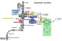
Drawing 5. Fat control gear
(type GA VIII gyro to the right, pattern gear to the left) [1]
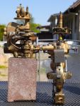
Photo 1. Fat control gear
(type GA VIII gyro to the right, pattern gear to the left)
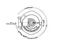
When the torpedo left the tube, it turned by pre-set angle (so called gyro angle, Germ. Schußwinkel) and then run straight. Both turn and straight run was controlled by type GA VIII gyro. The spinning gyro disc determined the fixed reference plane in space (this plane was perpendicular to the longitudinal axis of the torpedo tube). The gyro angle was set relative to this reference plane. The gimbals were coupled with pneumatic steering-engine which actuated the rudder of the torpedo. The gyro angle was set by rotation of the setting spindle (Germ. W-Einstellspindel), which was located at the aft part of the torpedo hull, at right side (one turn of the setting spindle was equal to the 2° of gyro angle).

Photo 2. Type GA VIII gyro

Photo 3. The gyro angle setting spindle
(loading the G7e electric torpedo into the aft torpedo room of the type IX U-Boat)
The Fat pattern gear consisted of several cams: the cam controlling the length of the preliminary straight run (Vorlaufscheibe), the set of four steering cams controlling the pattern (Steuerscheibe rechts kurz, links kurz, rechts lang, links lang) and the setting cam (Nockenscheibe), used for selecting one of four steering cams.
Drawing 6. Fat pattern gear [1]
| Steuerscheibe rechts, lang | the steering cam, pattern rechts, lang |
| Steuerscheibe links, lang | the steering cam, pattern links, lang |
| Steuerscheibe rechts, kurz | the steering cam, pattern rechts, kurz |
| Steuerscheibe links, kurz | the steering cam, pattern links, kurz |
| Vorlaufscheibe | the cam for controlling the length of the preliminary straight run |
| Nockenscheibe | the setting cam |
| Steuerscheibeneinstellhebel | the setting cam follower |
| Steuerhebel | the steering cam follower |
| Anlaßschieber | the starting valve |
| Verteilungsschieber | the control valve of the Fat steering engine |
| Steuerkolben | the control piston of the Fat steering engine |
| GA | the steering engine of the GA gyro |
| Kolbenstange | the steering engine linkage |
| Anschlagbolzen | the pneumatically controlled coupling |
| GA-Ruder | the torpedo rudder |
| Einstelspindel | Fat setting spindle |
| Luft: 6 kg/cm2 vom GA-Regler | the compressed air (6 kg/cm2) supply from the gyro reducing valve |
| Sperrklinkeneinrichtung | the unidirectional clutch |
| Maschinenschott | the bulkhead between engine compartment and aft compartment |
| biegsame Welle | the flexible drive shaft |
| Schneckenrad der Stoppvorrichtung u. Rudersperrung | the worm wheel of the engine stoping gear and depth rudder locking gear |
| Schnecke der Maschinenwelle | the worm at the drive shaft |
The lateral surface of the setting cam was divided into four parts, which corresponded to the four maneuvering patterns. The setting cam follower (Steuerscheibeneinstellhebel) slid the set of four steering cams into the one of four positions. In each position only one steering cam had a contact with the steering cam follower (Steuerhebel). The steering cam follower was actuated by currently selected steering cam. The follower was coupled with the pneumatic steering engine (Verteilungsschieber + Steuerkolben), which in turn, by means of the pneumatically controlled coupling (Anschlagbolzen), was coupled with pneumatic steering engine of the gyro (GA). The steering cam had a rounded shape with two pairs of indentations and two pairs of notches for rechts lang and links lang cams, and three indentations and three notches for rechts kurz and links kurz cams. The indentation forced the right turn, while the notch the left run.
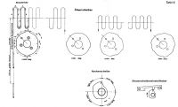
Drawing 7. The steering cams, maneuvering patterns and setting cam [1]
| Steuerscheiben | the steering cams |
| Ablaufstrecke | torpedo track |
| Nockenscheibe | the setting cam |
| Steuerscheibeneinstellhebel | the setting cam follower |
| 150 hm; größte Vorlaufstrecke | 150 hm; the greatest length of the preliminary straight run |
| 1,5 hm; kleinste Vorlaufstrecke | 1,5 hm; the smallest length of the preliminary straight run |
The steering cam follower was actuated by preliminary straight run cam. The lateral surface of this cam was divided into two parts (of the same length). The first part controlled the straight run, while the second part controlled the pattern running. During the first stage of run (preliminary straight run) of the torpedo, the preliminary straight run cam kept the steering cam follower away from the steering cam. The length of the preliminary straight run depended on the initial position of the cam. When the cam was trained sufficiently, it allowed the steering cam follower to get in contact with the steering cam. Additionally, the steering cam follower opened the starting valve (Anlaßschieber), enabling the pneumatically controlled coupling (Anschlagbolzen), hereby establishing the mechanical connection between Fat steering engine and gyro steering engine. The starting valve also supplied the compressed air to the Fat steering engine (which was necessary for operation the steering engine).
Drawing 8. The preliminary straight run cam [1]
| Schleifenlauf | pattern running |
| Marke am Gehäuse | the mark at the housing |
| 1,5 hm bis 150 hm Vorlaufstrecke | preliminary straight run length in range 1,5 hm to 150 hm |
| Achtung auf richtige Stellung der Hubnockenmarke! | watch out for the proper position of the cam mark! |
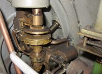
Photo 4. The Fat pattern gear of the G7a (T I) wet-heater torpedo
The length of the preliminary straight run (Vorlauf) and pattern mode (Schleifenlauf) was set by means of the single setting spindle (Germ. Fat-Einstellspindel), which was located just in front of the gyro angle setting spindle (Germ. W-Einstellspindel).
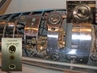
Photo 5. The Fat setting spindle and gyro angle setting spindle of the G7e electric torpedo in the MSI, Chicago
The Fat setting spindle rotated (by means of the gear of ratio 4:1) the preliminary straight run cam and at the same time (by means of the worm gear of ratio 16:1) the setting cam. Since only the half of the Vorlaufscheibe was designated for controlling the preliminary straight run, to set the correct value, the spindle could be rotated only so much as two turns. In the same time the setting cam would rotate only so much as 1/8 turn. Because the setting cam is divided into four parts (corresponding to the four steering cams), the current steering cam would not change (the cam would turn only so much as half of the quarter of the cam). Only after the next two turns of the spindle, when the Vorlaufscheibe was trained into its initial position, the setting cam turned by the following 1/8 turn (i.e. the second half of the quarter of the cam), moving the set of steering cams into the next position (enabling the next steering cam).
In other words, the first two turns of the setting spindle set the preliminary straight run length for the first maneuvering pattern, after next two turns the steering cam is changed and the length of the preliminary straight run can be set for the currently selected steering cam, and so on.
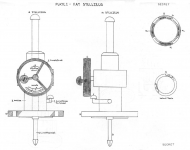
The dedicated setting device (Germ. Fat-Stellzeug) attached to the torpedo tube was used to make correct setting of the length of the preliminary straight run and pattern mode of the torpedo loaded into the tube.

Drawing 9. Fat setting gear [1]
Drawing 10. The drawing of the Fat setting gear made during the interrogation of the survivors from U 664 [2]
The Fat setting gear consisted of the hand-wheel, two coaxial discs (one of them presents the length of the preliminary straight run, while the other the current maneuvering pattern) and the handle (when pressed, the Fat setting spindle was retracted into the tube and torpedo). If any of the discs showed Falsch label, the setting was invalid. The Falsch label at the external disc (showing the length of the preliminary straight run) corresponded to the part of the Vorlaufscheibe, which allowed for the contact of the steering cam follower with the steering cam. The Falsch label at the internal disc (showing the maneuvering pattern) corresponded to the second halves of each quarter of the setting cam. Leaving the setting cam in such position meant that during torpedo run, the setting cam turned into the position corresponding to the next steering cam. That meant undesired change of the maneuvering pattern during the torpedo run. The hand-wheel could be trained only counter clockwise, so when the desired setting was missed, it was necessary to train the hand-wheel by 16 turns to set it again.
When the torpedo was launched, the cams where turned (by means of the flexible driving shaft) by forward end of the engine shaft (through the unidirectional clutch, so while the cams were trained by the Fat setting gear, the engine shaft was still). The engine shaft revolutions corresponded to the distance traveled by torpedo (similarly as in case of the stop and rudder locking gear, Germ. Stoppvorrichtung und Rudersperrung).
As one can see, the Fat pattern gear had nothing to do with spring gear, as the German name Federapparattorpedo suggests. Most likely, the name comes from the first version of the pattern gear, which based on the clockwork (Germ. Federwerk).
The extensive trials were conducted on 2 October 1942 by TVA and TEK (Torpedoerprobungskommando, Torpedo Trials Department) with complicity of 25th U-Boat Training Flotilla in Gdańsk Bay (Germ. Danziger Bucht). The exercise convoy attacks conducted by U 268 in presence of BdU Karl Dönitz, BdU deputy (2. Admiral der Unterseeboote) von Friedeburg, Chief of the Torpedo Office (Amt Torpedowaffe) Vice-Admiral Otto Backenköhler and Chief of the TI (Torpedoinspektion, Torpedo Inspection) Admiral Otto Ciliax, proved effectiveness of the new weapon. BdU found the Fat torpedo ready to combat usage and ordered to enter it to the service as fast as possible.
Because the visible wake of the G7a wet-heater torpedo (the bubbles of the exhaust gases) could betray the maneuvering feature of the Fat torpedo, to keep it in secret as long as possible (and to prevent any counteraction), it was ordered to use it at night only.
In order to use Fat torpedo effectively, the length of the preliminary straight run (Vorlauf) had to be set properly. If length was too long or too short, the torpedo started to maneuver behind and in front of the convoy respectively, being completely useless.
Drawing 11. Too short, too long and optimal length of the preliminary straight run (Vorlauf)
On 19 October 1942, BdU and MND (Marinenachrichtendienst, Naval Intelligence Office, supervising the research, development and manufacture of the radar equipment for Kriegsmarine) decided to arm with Fat torpedoes the U-Boats that were equipped with the new type FuMO 30 radar set. Owing to the radar, during the convoy attack, the accurate distance to target in the moment of torpedo launch (Schußentfernung) could be measured, which later should be (for instance by means of the torpedo calculator) converted to the length of the preliminary straight run (Vorlauf). The first U-Boats were to be ready to service in the mid-November 1942, however due to shortage of the radar sets, the installation works lasted until the end of December 1942. Because of this delay, for about 1 month, 10 combat ready U-Boats stayed in yards instead of North Atlantic. According to BdU, this resulted in the decreasing of the sinking ratio in the end of 1942.
Drawing 12. Distance to the target (Schußentfernung) and length of the preliminary straight run (Vorlauf)
On 8 November 1942, BdU foreseeing (based on the intelligence) large convoy operation in the West Mediterranean, ordered to arm with Fat torpedoes the U-Boats operating in Mediterranean (indeed, it was the allied operation Torch). The 24 Fat torpedoes stored in Kiel were to be transferred to Mediterranean bases of the 29th U-Boat Flotilla: 6 torpedoes to Pola (at that time in Italy, nowadays in Croatia) and 18 torpedoes to La Spezia (Italy).
The shipyards technicians had to be sent there from Kiel, who were to adjust the torpedo tubes to the new type of torpedo. In practice it was required to drill one hole in the tube and install the Fat setting gear. Due to lack of time (and limited number of torpedoes), only two torpedo tubes of four U-Boats (U 83, U 373, U 453 i U 562) were to be modified. Each U-Boat was to carry six Fat torpedoes. The schedule was as follows:
| U 375 | Pola | 17.11.1942 |
| U 562 | La Spezia | 22.11.1942 |
| U 453 | La Spezia | 28.11.1942 |
| U 83 | La Spezia | 29.11.1942 |
This schedule was not executed. Perhaps BdU realized that few Mediterranean U-Boats armed with new torpedoes in the end of November did not influence on Torch operation (after seizing harbors in Morocco and Algeria on 8 November, regular supply convoys to Africa were established: UGF and UFS from USA to Gibraltar, KMF and KMS from UK to Mediterranean). Anyway, based on analysis of U-Boats War Diares one can say that none of these four U-Boats was fitted with Fat torpedoes until the end of 1942.
Of the Mediterranean U-Boats, the first U-Boat armed with Fat torpedoes was U 73 in La Spezia, just before her 10th war patrol (which began on 1 December). However, they were used (most likely) on her next patrol, during an unsuccessful attack on convoy, on 26 December 1942.
The BdU War Diary contains an entry (on 29 November 1942) saying that the first Atlantic U-Boat on war patrol with Fat torpedoes was U 533. This boat left St. Nazaire on her 9th war patrol on 23 November. On 9 December the U-Boat attacked convoy HX-217, launching two salvos (2 torpedoes each). Among the launched torpedoes could be Fat type. The first salvo hit and sunk British motor merchant Charles L.D.
On 14 December 1942 U 406 left St. Nazaire for her 4th war patrol. At night 28/29 December 1942, during the attack on convoy ONS-154 five torpedoes were launched (including two Fat torpedoes), which hit and damaged British steamers Baron Cochrane, Lynton Grange and Zarian.
The survivors from U 662 (sunk on 21 July 1943) testified that at night 28/29 December 1942 during the attack on the same convoy ONS-154 the salvo of two Fat torpedoes were launched. The salvo missed the target. It was their 2nd war patrol, which begun on 19 December 1942 in Lorient.
Because of the delays in arming the U-Boats with Fat torpedoes resulting from the deficiency of the radar sets, on 8 January 1943 BdU ordered to arm with Fat torpedoes as many U-Boats as possible, irrespective from available radar sets. During the operation of U 406 against the convoy ONS-154 the distance to the target was estimated by eye, which appeared to be accurate enough conduct successful attack with Fat torpedoes (wherein BdU sensitize the commanders that it was better to overestimate the distance than underestimate).
At the same time, the usage of the Fat torpedoes at Mediterranean was prohibited due to operational difficulties (the torpedo wake was visible even at night because of water clarity and high phosphorescence). The Fat torpedoes were allowed for usage on the Northern Waters (Norwegian Sea, Barents Sea and Kara Sea) instead. On May 1943 the usage of Fat torpedoes on the Northern Waters was cancelled, because of the Midnight Sun, lasting from the end of April till the end of the August. During that time the torpedo wake was visible around the clock. It was planned to allow usage of the torpedoes again, when the Midnight Sun ended.
So since May 1943 the Fat torpedoes were operationally used only on Atlantic.
The Fat torpedoes launched toward the convoy, endangered not only the ships but also other U-Boats attacking the same convoy within the wolfpack. The most endangered were U-Boats inside the convoy. Therefore, the U-Boat that intended to attack with Fat torpedoes was obligated to transmit a special radio message, so called "Fat warning" (Germ. Fat Warnung) several minutes before the attack. The warning was valid for 30 minutes. After receiving such warning, the U-Boats inside the convoy had to run away or to dive to depth at least 50 meters.
Midshipman Hans-Jürgen Zupke (who in 1943 passed the dedicated training of Fat torpedoes in Brest) testified that Fat warning was supplemented with the information about intended maneuvering pattern (Zupke was one of 9 survivors from U 439, which sunk on 4 May 1943 after collision with U 659, west to the cap Cabo Fisterra).
Besides the single shots, to enlarge the danger zone (and to increase the possibility of hitting) the salvo shots were used. The salvo could contain two, three or four Fat torpedoes. The general rule was to set the maneuvering pattern alternately: kurz and lang. Additionally, each torpedo in salvo could be set to slightly different length of the preliminary straight run.
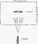
Drawing 13. The Fat salvo, the drawing made during the interrogation of the survivors from U 664 [2]
The production rate of the Fat torpedoes was only 100 per month. The low rate resulted from the high labor intensity during manufacturing the G7a wet-heater torpedoes, manufactured at rate 350 per month. Some of them were intended for torpedo training at Baltic Sea while the others for torpedo boats. So only small number of the torpedoes could be modified to maneuvering version.
The pattern running type G7a Fat wet-heater torpedo could run only at speed of 30 knots (the speed setting WS – Weitschuss). At that speed the torpedo range was the largest (equal to 12 km). Moreover, the G7a torpedo turning with radius 170 m at speed greater than 30 knots did not keep depth properly. Therefore the development was continued to have the wet-heater torpedo able to maneuver with speed of 40 knots (the speed setting NS – Nahschuss). Finally, the results were not satisfying and only 30 knots version of the Fat torpedo was used in action.
At the same time, while working on the pattern running wet-heater torpedo, the maneuvering version of electric torpedo G7e was in development. As far as the Fat pattern gear created for wet-heater torpedo could be used in electric torpedo (which was fitted with the same gyro control system), the main problem was its small range, only 3 km (5 km after heating the torpedo battery up to 30° C).
The type T II electric torpedo was driven by electric motor powered by the type 13 T 210 acid-lead battery, manufactured by Accumulatoren-Fabrik (AFA). The battery consisted of two ebonite containers. Each container enclosed 26 cells connected in series. Each cell was built of 13 positive plates and 14 negative plates. The output voltage of each container was equal to 46 V. Two containers were connected in series, building the type 13 T 210 battery, of output voltage of 91 V, capacity of 85 Ah (93 Ah after heating up to 30°C) and weight of 665 kg. The torpedo powered by this battery could travel 3000 m (5000 m after heating up to 30°C) at speed 30 knots.
The combat ready type T II torpedo weighed 1606 kg, whereas its buoyancy was equal to 1306 kg, wherein the center of gravity was located about 40 cm behind the center of buoyancy (about 2 cm closer than in case of type T I torpedo). As the result of net forces, the submerged torpedo was turned around transverse axis (crossing the center of buoyancy), forcing the vertical position, with torpedo stern down.
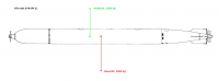
Drawing 14. The gravity and buoyancy forces acting on the type G7e (T II) electric torpedo
To counteract this rotation (and to keep horizontal orientation of the torpedo), the depth rudder had to be deflected slightly down (by the so called free angle, Germ. freie Winkel). The water flowing the depth rudder generated the hydrodynamic force, directed upward. This force lifted the stern of the torpedo, thus preventing the rotation of the torpedo to the vertical position. In other words, the torpedo cruising at preset depth had depth rudder deflected down by few degrees (rather than in horizontal position, as it would be in case of the torpedo, of which the center of gravity overlaps the center of buoyancy).
The type T II torpedo had negative buoyancy of 300 kg and as a result it sunk. To counteract the negative buoyancy, the hydrodynamic force generated by torpedo hull was used. For this purpose the torpedo had to cruise with stern slightly lower than the head, so the longitudinal axis was inclined to the horizon at the angle called attack angle (Germ. Anstellwinkel). This attack angle was gained by decreasing the free angle value corresponding to the horizontal orientation of the torpedo. The free angle was set by adjusting the length of the linkage between depth gear steering engine and depth rudders.

Drawing 15. The free angle γ and attack angle α [3]
In the end of 1941, as a solution of the type T II torpedo short range problem it was proposed that after traveling the preliminary straight run (i.e. just before beginning of pattern running), the two 26-cell containers of type 13 T 210 battery were switched from the serial to parallel connection. Thus the output voltage powering the motor dropped to 46 V, so the speed decreased down to 20 knots, however the capacity of the battery was doubled. As a result the remaining range of torpedo was tripled (for instance, when length of the preliminary straight run was set to 1000 meters, the remaining range was 12000 meters at speed 20 knots instead of 4000 meters at speed 30 knots). During the trials it appeared that in the moment of switching batteries, when the speed changed from 30 to 20 knots, the torpedo rapidly decreased the depth (the pendulum of the depth gear, due to inertia, was moved forward when speed decreased, which was the same result as the head moved down, so the depth gear steered the torpedo up). Moreover, the torpedo powered this way could not be armed with new influence pistol Pi 2 (which entered service in the end of 1942), because it required the powering by the battery with full output voltage of 91 V. Additionally, the torpedo cruising with lesser speed required greater attack angle (Anstellwinkel) to counteract the negative buoyancy. The trials proved that when the torpedo was cruising with greater attack angle, it started to heel oscillatory. The heeling appeared to be serious problem because it could cause leakage of battery electrolyte (if heel angle greater than 20°). Moreover, in the moment of hitting the target, the heeling of the torpedo increased the chance for failure of the type Pi G7a or Pi 1 impact pistol.
The heeling was removed by increasing the area of the vertical stabilizers. The size of the vertical stabilizers of previous types of torpedoes was restricted by internal diameter of the torpedo tubes (equal to 553 mm). To avoid this restriction, the extensible vertical stabilizers (Germ. ausschiebbare Flossen) were used. These were additional stabilizers, whose contour in the resting position (in which were held by springs) overlapped with actual vertical stabilizers. These additional stabilizers were extended by pneumatic pistons, supplied with compressed air (under pressure of 6-8 kg/cm2), from the gyro reducing valve (Regler für G A). In the moment of the torpedo launch, simultaneously with starting the motor, the main air valve was opened and enabled compressed air supply (by means of the gyro reducing valve) to the gyro, steering engines and pistons of the extensible vertical stabilizers. As soon as the torpedo cleared the tube, the pneumatic pistons extended the extensible stabilizers, increasing their lateral area by about 30%. The larger lateral area of the vertical stabilizers resulted in heeling extinction and increased the stability of the torpedo.

Drawing 16. The pistons extending the extensible vertical stabilizers
| Flossen in Ausgangsstellung | the stabilizers in the resting position |
| Flossen in ausgeschwenkter Stellung | the stabilizers in extended position |
| Kolben für ausschiebbare Flossen | the pistons extending the vertical stabilizers |
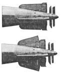
Photo 6. The extensible vertical stabilizers [4]
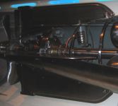
Photo 7. The extensible vertical stabilizers of the type G7e electric (Fat II) torpedo exhibited in MSI, Chicago (the pneumatic piston for extending the stabilizer is visible)
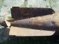
Photo 8. The top extensible vertical stabilizer of the type G7e electric (Fat II) torpedo exhibited in Muzeum Obrony Wybrzeża, Świnoujście (the upper part of the pneumatic piston for extending the vertical stabilizer is visible)

Photo 9. The extensible vertical stabilizers of the type G7e electric (Fat II) torpedo exhibited in Muzeum Obrony Wybrzeża, Świnoujście (the pneumatic piston extending the top vertical stabilizer is visible)
Although the problem with oscillatory heeling was solved, the concept of battery switching in order to increase the torpedo range was abandoned.
In the meantime, in the end of 1942, the new electric torpedo (designated as T III) entered the service. The new torpedo was a slightly modified type T II torpedo. Germans simply added a cable between battery compartment and head of torpedo, in order to provide power supply for the new type Pi 2 influence pistol.
For a very brief time, the Fat control gear was installed (despite a short range of maximum 5000 meters) in type T II and T III electric torpedoes.
In the beginning of 1943, the AFA company was ordered to develop the torpedo battery of greater capacity. In the Spring, AFA company delivered new type 17 T 210 battery, which consisted of two containers, 26-cell each. Each cell was built of 17 positive plates and 18 negative plates. The total capacity was equal to 130 Ah (when heated up to 30°C). The newly developed electric torpedo (designated as T IIIa) was powered by this type 17 T 210 battery and two additional cells (54 cell in total). Such arrangement provided energy for travelling (after heating up to 30° C) 7500 meters. The weight of type 17 T 210 battery was equal to 800 kg.
The extended running time (by over 2,5 minutes) required the larger compressed air storage (which was used to drive the gyro and steering engines). In the type T II and T III electric torpedoes, the compressed air was stored (under the pressure of 200 at) in three flasks of capacity 5 liters each, located in the aft part of the torpedo. The type T IIIa torpedo was fitted with additional spherical tank of capacity 15 liters, located in the forward part of the battery compartment.
The greater weight of the type 17 T 210 battery and additional compressed air tank increased the weight of the type T IIIa torpedo (comparing to the the weight of the type T II and T III torpedoes) by about 200 kg. Therefore, the negative buoyancy increased up to 500 kg. The increased negative buoyancy required to be compensated by increasing the hydrodynamic force generated at the torpedo hull. This in turn required greater attack angle. The greater attack angle was related with oscillatory heeling, which (apart from the leakage of the electrolyte) could result in premature activation of the type Pi 2 influence pistol. That's why type T IIIa torpedoes were fitted with (developed earlier, quite effective) extensible vertical stabilizers (ausschiebbare Flossen).
The Fat control gear for type T IIIa torpedoes was almost identical to the control gear for type T I wet-heater torpedoes. The main difference between them was a different set of the steering cams, and hence a different maneuvering patterns. Moreover, Fat control gear for the electric torpedoes was driven directly from the torpedo propeller shaft.
The available maneuvering patterns were lang links/rechts (the same as in case of wet-heater torpedoes, of the loop length of 1200 meters and 1800 meters). However, instead of kurz links/rechts pattern, the circling (to the left) pattern (of radius of 170 meters), so called Kreislauf was introduced. It was intended to use this circling pattern to self-defense against the destroyers attacking the U-Boat (as a temporary weapon, until the new type T V "Zaunkönig" homing torpedo entered the service).
However, the type T V homing torpedo entered the service in September 1943, so electric Fat torpedoes did not have opportunity to gain any successes in the anti-destroyer role.
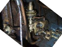
Photo 10. The Fat pattern gear of the type G7e (T IIIa) electric (Fat II) torpedo, exhibited in Muzeum Obrony Wybrzeża, Świnoujście (comparing to the Fat pattern gear of the G7a wet-heater torpedo, one can note that bottom steering cams are identical and that pattern gear is driven directly from the propeller shaft)
Despite the different maneuvering patterns and shorter range (and hence shorter length of the preliminary straight run), it was decided not to develop different Fat setting gear. In the end of March 1943, the order was issued to use Fat setting gear dedicated for wet-heater torpedoes. The circling pattern was corresponding to the maneuvering pattern kurz (links or rechts).
Because electric torpedo was wakeless, the Fat torpedoes entered the service at first (in May 1943) in the areas, were wet-heater Fat torpedoes could not be used, i.e. on Mediterranean and Norther Waters (Norwegian Sea, Barents Sea and Kara Sea). Since June 1943, the Atlantic U-Boats were armed with electric Fat torpedoes, so they could use them to attack targets during the day, while submerged. Due to shorter range of the electric Fat torpedoes, it was found that other U-Boats in vicinity were not endangered and therefore there was no necessity to transmit the "Fat warning" before the attack.
In the initial period, the production rate of electric Fat torpedoes was only 100 per month.
Since the beginning of 1943, there were two, almost identical Fat control gears, designated for two types of torpedoes (wet-heater and electric torpedo), therefore, since the end of March 1943, the maneuvering versions of type T I wet-heater torpedoes (until then designated as Fat) were designated as Fat I, while maneuvering versions of the type T IIIa electric torpedoes were designated as Fat II.
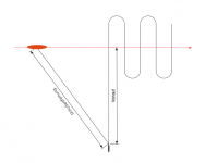
The new terms: so called "Fat speed" (Germ. Fat-Geschwindigkeit) and so called "Fat course" (Germ. Fat-Kurs) are related with Fat torpedoes.
"Fat course" describes the general direction of the maneuvering torpedo, while "Fat speed" is the speed of advance along the "Fat course".

Drawing 17. The Fat speed and course (maneuvering pattern rechts kurz)
The "Fat course" is always perpendicular to the initial course of the torpedo, before it started to maneuver. To increase the chance for hitting the target, the "Fat course" should be parallel to the convoy general course.
The "Fat speed" depends on the length of the loop. For kurz pattern, this speed is equal to 8.5 knots, while for lang pattern, the speed is equal to 5.3 knots. The greatest chance for hitting the target in convoy is when the speed of convoy and "Fat speed" differs slightly. Therefore, the "Fat speed" for patterns kurz and lang were so adjusted to be close to the speed of the fast (of the speed 9-10 knots) and slow (of the speed 6-7 knots) convoys.
When Fat torpedoes entered the service, the only necessary adjustment required of the torpedo tubes was to drill the hole in the tube (for the Fat setting spindle) and to install Fat setting gear (Fat-Stellzeug).
It should be noted that torpedo tube with Fat setting gear installed could be also used to launch straight running, type T I wet-heater torpedoes as well as straight running type T II and T III electric torpedoes.
Likewise, the pattern running Fat I and Fat II torpedoes could be launched from the unmodified torpedo tubes (not fitted with Fat setting gear). Before loading to the unmodified tube, the maximum length of the preliminary straight run (Vorlauf) should be set at the torpedo. Then the launched torpedo acted as straight running torpedo.
The attack with Fat torpedoes was conducted in the similar way as in case of straight running torpedoes: the target data (speed and angle on the bow) were determined, then they were entered into the torpedo calculator. The calculator calculated the gyro angle, which was set at the torpedoes by means of the gyro angle setting spindle (W-Einstellspindel).
Then the distance to the target was estimated (or measured by radar), which (by means of the component for calculating maximum distance to target at the moment of the torpedo launch) was used to calculate the length of the preliminary straight run (Vorlauf).

Drawing 18. Distance to the target (Schußentfernung) and length of the preliminary straight run (Vorlauf)
Drawing 19. Reading out of the length of the preliminary straight run (Vorlauf) based on the distance to the target (Schußentfernung) from the component for calculating maximum distance to target at the moment of the torpedo launch
The calculated length of the preliminary straight run as well as selected maneuvering pattern (according to the speed and direction of convoy) was set by means of the Fat setting gear at the torpedo.
To make calculations of the length of the preliminary straight run easier, since 1943, the drum of the component for calculating maximum distance to target at the moment of the torpedo launch was fitted with new, detailed scale (instead of 7 lines corresponding to the maximum ranges of the German torpedoes, 24 lines were provided).
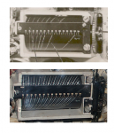
Photo 11. The component for calculating maximum distance to target at the moment of the torpedo launch: early version (before 1943) and late version (after 1943)
The U-Boats were armed with Fat torpedoes as soon as they were available particular torpedo depots, according the directives issued by BdU.
| 10.05.1943 | |||
| U-Boat type | Bow torpedo room | Aft torpedo room | Upper deck |
| Atlantic Ocean | |||
| VIIB, VIIC, VIID | 4 Fat I, 6 T III | 2 Fat II | |
| IXB, IXC | 4 Fat I, 6 T III | 2 Fat I, 2 Fat II | |
| IXD | 6 T III, 4 G7e | 4 G7e | 12 G7a |
| XB | 2 Fat II, 2 G7e | only if ordered | |
| Mediterranean and Northen Waters | |||
| VIIB, VIIC | 4 Fat II, 6 T III | 2 Fat II | |
| Black Sea | |||
| II | 5 T III | ||
| South Atlantic and Indian Ocean | |||
| IXC | 6 T III, 4 G7e | 2 Fat II, 2 G7e | |
| 01.04.1944 | |||
| U-Boat type | Bow torpedo room | Aft torpedo room | Upper deck |
| Atlantic Ocean | |||
| VIIC | 3 T V, 2 Fat I, 3 T III Fat II (or 5 T IIIa Fat II) |
2 T V | |
| VIID | 2 T V, 2 Fat I, 4 T III Fat II | 2 T V | |
| IXB, IXC | 3 T V, 3 Fat I, 4 T III Fat II (or 7 T IIIa Fat II) |
2 T V, 2 T III Fat II | |
| IXD | 2 T V, 8 T III Fat II (or 8 T IIIa Fat II) |
2 T V, 2 T III Fat II | 9 Fat I (or T I) |
| XB | 2 T V, 5 T III (or 5 Fat II) |
||
| Mediterranean | |||
| VIIC | 3 T V, 5 T IIIa Fat II | 2 T V | |
| Northen Waters | |||
| VIIC | 3 T V, 5 T III Fat II | 2 T V | |
| In case of U-Boats operating on Northen Waters, when Midnight Sun ended (i.e. since the end of August), three T I Fat I torpedoes would be loaded instead of three T III Fat II torpedoes. | |||
| Morze Czarne | |||
| II | 1 T V, 4 T III | ||
| 01.11.1944 | |||
| U-Boat type | Bow torpedo room | Aft torpedo room | Upper deck |
| Atlantic Ocean | |||
| VIIC | 3 T V, 5 T IIIa Fat II | 2 T V | |
| IXC | 4 T V, 5 T IIIa Fat II | 2 T V, 2 T IIIa Fat II | |
| IXD | 2 T V, 8 T IIIa Fat II | 2 T V, 2 T IIIa Fat II | 9 T I Fat I |
| XXIII | 2 T IIIa Fat II | ||
| Northen Waters | |||
| VIIC | 3 T V, 5 T IIIa Fat II | 2 T V | |
| Baltic Sea | |||
| VIIC | 3 T V, 5 T IIIa Fat II | 2 T V | |
Generally, initially the U-Boats were armed with Fat torpedoes according the following standard: Fat I torpedoes were loaded into forward torpedo room, while Fat II torpedoes were loaded into aft torpedo room. Fat II torpedoes (in circling mode) launched from aft tubes were intended to be anti-escort weapon. Only U-Boats operating on Mediterranean and Northern Waters received Fat II torpedoes only.
When type T V "Zaunkönig" homing torpedoes entered the service, they were designed as anti-escort weapon, loaded into aft tubes. The Fat II torpedoes (released from anti-escort function) began to be loaded into forward torpedo rooms.
Since November 1944, the U-Boats were armed with wake-less Fat II and T V electric torpedoes only (concerns only the U-Boats with tubes adjusted to Fat torpedoes).
The pattern running Fat were used since November 1942 until March 1945. At least 100 U-Boats were armed with them. At least 60 attack were conducted with maneuvering torpedoes. It is difficult to present more accurate statistics without thorough query of the U-Boats War Diaries (and associated firing reports, Germ. Schussmeldungen) of the particular boats (however such query does not guarantee success, because torpedo type was not always noted).
References:
[1] Federapparat für den Torpedo G7a Fat I, Beschreibung, Zeichnungen und Bedienungsvorschrift, 1942
[2] Report on the Interrogation of Survivors from U-664
[3] Manfred Schiffner, Karl-Heinz Dohmen, Ronald Friedrich, Torpedobewaffnung
[4] Eberhard Rössler, Die Torpedos der deutschen U-Boote
The torpedo attacks descriptions in the U-Boat War Diaries, usually (beside the result: hit/miss) contained the attack data. Moreover, after each torpedo attack a dedicated report (Schussmeldung) was written down. This report contained all details of the attack. Based on these reports, the analysis of the attacks effectiveness could be made and in case of the unsuccessful attacks, the reason of failure could be determined.
However, the most interesting diaries entries (regarding the subject of this website) are those describing malfunctions of the torpedo fire control system and proceeding in such cases.
Several cases of the torpedo attacks conducted by means of the damaged fire control systems are described below.
The description of the usage of the fully-operational torpedo fire control system is available here.
U 48's attack on convoy HG-34F, 19 June 1940 (grid BE 9651)
Auf ersten und zweiten Dampfer der Westreiche angelaufen. E = etwa 1200 – 1000 m.
Torpedoschuß aus Rohr I fällt nicht.
UZO Übertragung zur R.W. ausgefallen. Kabel abgesoffen. Schuß aus Rohr IV nach Vorhalttabelle. Vorhalt zu groß! Vorne vorbei!
Abgedreht. Dabei und durch das durch Warten auf Fallen der Schüsse auf etwa 500 m an Schlußschiff herangekommen. Wir hören ihn während des Ablaufens heulen. Seitlich und hinter des Geleitzug keine Sicherung. Morseverkehr.
Die marine Warnung und grüne und weiße Sterne beobachtet. Außer Sicht vom Geleitzug vorgelaufen. Der Feger steht noch vorn, läßt sich anscheinend nicht aus der Ruhe bringen.
Die Dampfer haben sich inzwischen wieder in die Formation gefunden. Wieder angelaufen.
Schuß aus Rohr III fällt auf etwa 1000 m.
Abgedreht zu Heckschuß. Nach 114 Sek. = 1600 m traf der Schuß aus Rohr III einen überlappend stehendes Schiff das weiter entfernt war. Größe etwa 6500 t. Heckschuß ist Fehlschuß, da in der Eile Vorhalt nicht in G.A. eingedreht. Abgelaufen.

Photo 1. The U 48's War Diary, 19th June 1940, the entry describes the attack on the convoy HG-34F [1]
Ran toward the first and second steamers in the western column. Range: 1200 - 1000 meters.
Torpedo does not leave the tube I.
The transmission link between night sight UZO and torpedo calculator fails. Cable flooded. Shot from tube IV from deflection table. Deflection angle too great! Torpedo passed ahead!
Turned away. At the same time, by waiting on taking the attack position approached to approximately 500 meters from the closing ship, we hear him howling while moving off. Laterally and behind the convoy there is no screen. Morse traffic.
A naval warning of green and white stars observed. Maneuvered ahead out of sight of the convoy. The sweeper is still positioned ahead, apparently cannot be disturbed.
In the mean time the steamers are again found in the same formation. Again approached.
Shot from tube III taken at about 1000 meters.
Turned for a stern shot. After 114 seconds = 1600 meters the shot from tube III hit an overlapping ship that was further away. Size about 6500 tons. Stern shot missed, because in the rush the gyro angle not set at the gyro angle setting gear. Ran off.

Photo 2. Schussmeldung on U 48's torpedo attack on 19th June 1940 [1]

Photo 3. Schussmeldung on U 48's torpedo attack on 19th June 1940 [1]

Photo 4. Schussmeldung on U 48's torpedo attack on 19th June 1940 [1]
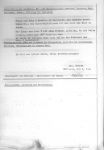
Photo 5. Schussmeldung on U 48's torpedo attack on 19th June 1940 [1]
During the first attack approach it was intended to launch two torpedoes. However, one of them did not leave the tube I (the torpedo was not a Rohrlaufer, i.e. a torpedo with running engine that got stuck in the tube, most likely the launching gear failed). While preparing the second torpedo to launch (from tube IV), it turned out that the target bearing from the UZO night sight was not transmitted to the torpedo calculator (because of damaged wire). In such a situation, it was decided to abandon the usage of the torpedo calculator and to launch torpedoes without gyro-angling (by aiming with the boat) with calculating tables. Accordingly, the UZO night sight was set to the bearing equal to 345°. The angle between the sight line and course of the straight (without gyro-angling) running torpedo was equal to 15°, i.e. the value of calculated deflection angle. The torpedo was launched when the target appeared in the sight graticule. In the War Diary was written that deflection angle was too great and torpedo passed ahead of the target. It seems that in a hurry, the mistaken value was read from the calculating tables: for firing data recorded in the firing report (Schussmeldung) (target speed 9 knots, angle on the bow 90°), the deflection angle should be 13°, while in the fact the value 15° was used. If the target was 1000 meters away (as recorded in the firing report), the torpedo passed about 35 meters ahead of the target.
The next attack (one hour later) was conducted by means of the partially operational fire control system, according to the procedure described in the chapter II A (Feste Seite). This procedure was provided in case of malfunction of the target bearing transmission link between night sight/periscope and torpedo calculator. As a fixed bearing angle, the value 0 was used (i.e. aiming at the bow net cutter). According to this procedure, the target data as well as the fixed target bearing equal to 0 were set at the torpedo calculator. Using these values, the device calculated the gyro-angle value equal to 16° (port), which was automatically transmitted and set (by means of the gyro-angle receiver in the bow torpedo room) at torpedoes. When the target was directly ahead of the U-Boat, visible above the bow net cutter (i.e. at bearing 0 for which the gyro-angle was calculated), the torpedo was launched.
The first torpedo launched in this way from the tube III hit the Norwegian motor merchant Tudor.
The next torpedo to the same target was intended to be launched in the same way from the stern torpedo tube. When the boat turned around, the torpedo was launched, but in a hurry the order for setting the target bearing 180° at the calculator was not issued (and most likely the gyro-angle receiver in the stern torpedo room was not enabled too). As a result, the torpedo was launched with the gyro-angle value equal to 0 (should be equal about 12°).
The next torpedo attacks that night were conducted in the same way. During the next day, the target bearing transmission wire was repaired and the subsequent attacks were conducted by means of the fully operational torpedo fire control system.
U 69's attack on not escorted, British steamer Tewkesbury, 21 May 1941 (grid ES 5554)
Angriff angesetzt!
Bug rechts, Lage 90°, Vg 10 sm, Ato 3 m.
Laufzeit 52 sec = 1070 m. Ohne Anlage, da G.A.
Stellzeug unklar!
Treffer: Vorn 20.
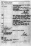
Photo 6. The U 69's War Diary, 21st May 1941, the entry describes the attack on the ship Tewkesbury [2]
Attack initiated!
Angle on the bow: 90°, bow right, target speed 10 knots, the wet-heater torpedo running depth 3 meters
Running time 52 seconds, 1070 m. Shot without fire control system, because
the gyro-angle setting gear is not working.
Hit, forward 20 meters.
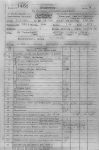
Photo 7. Schussmeldung on U 69's torpedo attack on 21st May 1941 [2]
Photo 8. Schussmeldung on U 69's torpedo attack on 21st May 1941 [2]
During this attack it turned out that gyro angle setting gears were out-of-order, so the gyro angle calculated by torpedo calculator could not be continuously set at torpedoes. In such a situation, it was decided to launch torpedo according to the procedure described in the chapter II B (Fester Schusswinkel) provided in case of such malfunction (although in the War Diary there is an entry: Ohne Anlage - without torpedo fire control system - content of the Schussmeldung clearly suggests Fester Schusswinkel procedure). According to this procedure, the target data were set at the torpedo calculator, and then by turning the target bearing knob, one tried to achieve the gyro angle equal to 0 as a result (this value of the gyro angle was also pre-set at torpedoes). Then, from the corresponding calculator dial, the target bearing (346°) was read off and passed to the bridge. The UZO night sight was set to this bearing and when the target appeared in the sight graticule, the torpedo was launched. As a result of this attack, the torpedo hit the stem of the British steam merchant Tewkesbury.
Just as a side note, the earlier attack on that day and the later attack (on 22nd May 1941) were also conduced without gyro-angling. However, the torpedoes were aimed to the stationary targets, so the deflection angle was 0.
The next attack (on 31st May 1941) was conducted with gyro-angling. It implies that gyro angle setting gears were repaired till then.
U 109's attack, 19 January 1942 (grid BA 9965)
Angelaufen zum Mehrschuss aus Rohr II und III.
S c h u s s aus Rohr II und III:
Eingestellte Werte:
Gegnerfahrt: 8 sm/h
Gegnerlage: 80 Bug links
Entfernung: 800 m.
Rohr III Schuss nicht gefallen, da Abfeuerungslampe im Bugraum nicht aufleuchtete und B.U.-Versager.
Fehlschuss!
Beim Seitenvergleich zwischen UZO u. Vorhaltrechner wurde ein Übertragungsfehler von 5° festgestellt, der vom Schützen beim Schuss berücksichtigt werden musste. Fälschlicherweise verlegte der T.O. den Abkommpunkt nach der verkehrten Seite.
Der UZO-Kopf war während der Letzten Tage vereist, und er musste beim Vergleich gewaltsam bewegt werden. Dabei scheint sich dieser Fehler von 5° eingedreht zu haben.
[…]
Angelaufen zum Schuss aus Rohr III (Ato)
S c h u s s aus Rohr III:
Eingestellte Werte:
Gegnerfahrt: 6 sm/h
Gegnerlage: 60 Bug links
Entfernung: 800 m.
Fehlschuss!
Laufzeit: Nach 6 Min. 58 Sec. Wurde im
Boot eine Torpedodetonation wahrgenommen, wahrscheinlich ist der Torpedo nach Ablauf seiner Laufstrecke auf flachem Wasser hoch gegangen.
Dampfer muss während des Anlaufs noch mehr mit der Fahrt heruntergegangen sein. Beim Abdrehen wird sofort Rohr VI klar gemacht, es sieht aus, als hätte der Dampfer gestoppt.
S c h u s s aus Rohr VI:
Eingestellte Werte:
Gegnerfahrt: 0 sm/h
Gegnerlage: 90 Bug links
Entfernung: 500 m.
Fehlschuss!
Schuss fielt mit falschem Schusswinkel.
Die Seite war nach dem Umschalten auf Heckrohre noch nicht nachgelaufen.
[…]
Setze mich vor zum Heckschuss aus Rohr V und laufe mit einer Maschine K.F., um Gegner ganz langsam einwandern zu lassen. Gegner wandert nur sehr langsam ein. Gegner läuft höchstens 4 sm/h.
S c h u s s aus Rohr V:
Eingestellte Werte:
Gegnerfahrt: 4 sm/h
Gegnerlage: 100 Bug links
Entfernung: 1500 m.
eingest. Tiefe am Torpedo = 2 m.
Auch dieser Schuss trifft nicht; obwohl die Schussunterlagen genau ermittelt waren.
Dieser Anlauf wurde mit festem Schusswinkel vom UZO geschossen. Wie später festgestellt, ist vom T.W.L. falscher Seitenwert am Vorhaltrechner abgelesen und an den T.O. gemeldet worden.
Auch dieser Torpedo muss zu allem Überfluss am Ende seiner Laufstrecke detoniert sein, denn im Boot wurde etwa nach 6 Min. eine Detonation wahrgenommen.
Ich gebe nun kein Vertrauen mehr zur Feuerleitanlage und ich entschliesse mich zu einem Schuss über den Netzabweiser mit festem Schusswinkel und festrer Seite 0°.
Setze mich etwas ab und vor zum nächsten Anflauf. Bb. Voraus ein weisses Licht, kommt schnell näher. Schmale Silhouette ist zu erkennen. Muss schnell zum nächsten Anlauf andrehen. Der Dampfer muss fallen!!
S c h u s s aus Rohr I über Netzabweiser:
Bin bis auf 500 m an den Dampfer herangegangen. Eingestellte Werte:
Gegnerfahrt: 4 sm/h
Gegnerlage: 90 Grad, Bug links
Entfernung: 500 m.
eingest. Tiefe am Torpedo = 3 m. da hohe lange Dünung.
Torpedo kommt nach 100 m aus des Wasser, läuft ein Stück als Oberflächenläufer und geht kurz vor dem Dampfer auf Tiefe.
Auch dieser Torpedo traf sein Ziel nicht.
Vermute, dass er den Dampfer untersteuert hat.
[…]
UZO überholt. Feuerleitanlage überprüft.
[…]
Aufgetaucht. Nochmals UZO an Hand der Nullmarke am Bug kontrolliert. Dabei festgestellt: UZO steht in Nullstellung in Mittschiffsrichtung. Fehler muss als in Übertragung vom UZO zum Vorhaltrechner liegen. Ausser Ausfall der Seitenübertragung ist Anlage klar.

Photo 9. The U 109's War Diary, the entry describes the attack on 19th January 1942 [3]
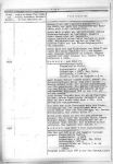
Photo 10. The U 109's War Diary, the entry describes the attack on 19th January 1942 [3]
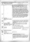
Photo 11. The U 109's War Diary, the entry describes the attack on 19th January 1942 [3]
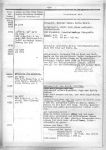
Photo 12. The U 109's War Diary, the entry describes the attack on 19th January 1942 [3]
Approached to fire multiple shots from tubes II and III.
Fired torpedo from tube II and III:
Firing data:
target speed: 8 knots
angle on the bow: 80, bow left
distance: 800 meters.
Tube III did not fire because the firing control lamp did not light up and the verbal command transmission failed.
Missed!
During comparison of the bearing transmitted by UZO and received by torpedo calculator a transmission error of 5° was noticed which had to be considered by the aimer when firing. However, the aimer erroneously corrected this error to the wrong side.
The UZO mechanism had been iced up in the last days and had to be moved with force for the aiming procedure, probably causing this 5° error.
[…]
Approached again to fire tube III (wet-heater torpedo)
Fired torpedo from tube III:
Firing data:
target speed: 6 knots
angle on the bow: 60, bow left
distance: 800 meters.
Missed!
After 6 minutes 58 seconds a torpedo detonation was heard in the boat, probably the torpedo exploded at the end of its run in shallow waters.
Steamer must have slowed down further during our approach. When turning away we immediately made tube VI ready, it looks like the steamer stopped.
Fired torpedo from tube VI:
Firing data:
target speed: 0 knots
angle on the bow: 90, bow left
distance: 500 meters.
Missed!
The torpedo was fired with the wrong gyro angle.
The torpedo calculator did not adjust the bearing after switching to the stern tubes.
[…]
I overtake the target to fire a stern torpedo from tube V and then wait with one engine at Slow-Ahead to let him run slowly into my line of fire. Enemy is approaching very slowly, running at 4 knots at most.
Fired torpedo from tube V:
Firing data:
target speed: 4 knots
angle on the bow: 100, bow left
distance: 1500 meters.
torpedo running depth: 2 meters.
This shot missed as well, despite exactly calculated firing data.
In this approach we fired with a fixed gyro angle from the UZO. Later we realized that the operator of the torpedo calculator read off a wrong value for bearing from the calculator and reported it to the aimer.
The torpedo detonated apparently at the end of its run because one could hear a detonation in the boat after about 6 minutes.
I've lost all confidence in the fire control system and decide to fire the next shot directly aimed with the net deflector on a fixed gyro angle and fixed bearing of 0°.
Headed off a bit to overtake for the next approach. Sighted a white light on port side ahead, comes closer fast. After recognized a slim silhouette we have to turn fast for the attack. This steamer has to fall!
Fired torpedo from tube I aimed with the net deflector:
Went closer to the steamer to a distance of 500 meters. Firing data:
target speed: 4 knots
angle on the bow: 90, bow left
distance: 500 meters.
torpedo running depth: 3 meters due to high and long swell
After 100 m the torpedo comes out of the water, runs a distance as surface runner and dives shortly before reaching the steamer.
This torpedo missed the target as well.
Assume that it passed underneath the steamer.
[…]
Overhauled the UZO and checked the torpedo data computer.
[…]
Surfaced. Again checked the UZO with the zero marker on the bow. In so doing noticed: UZO aims in the amidships direction when in the neutral position. The error has to be in the transmission from the UZO to the torpedo calculator. The fire control system is ready except the bearing transmission.
On 19th January 1942, near the southern coast of Nova Scotia, U 109 conducted five attacks on an unknown ship.
During the first approach it was intended to launch two torpedoes.
First of them was not launched because of failure of the electrical firing system, the respective control lamp indicating that firing lever was triggered also did not lit up (in response to lighting the lamp up, the torpedo tube operator should launch torpedo manually). The function of the control lamps was backed up by verbally passed orders through the voice tube or internal telephone (B.Ü. - Befehl Übertragung, e.g. Rohr eins... los!). However in this case, the passing orders also failed.
The second torpedo missed the target because wrong target bearing was transmitted to the torpedo calculator. Due to malfunction of the target bearing transmission system between UZO night sight and torpedo calculator, the value received by calculator varied by 5° from real value indicated by UZO. This flaw was observed before the attack, so the error was intended to be compensated by suitable adjustment of night sight. However, during the attack, the First Watch Officer took the lead to the opposite side, so the error was not compensated but increased to value of 10° and, as a result, the incorrect gyro angle was calculated.
The wet-heater torpedo launched during the second approach missed the target because of incorrect attack data (overestimated target speed).
During the third approach the torpedo was intended to be launched from the aft torpedo tube. After turning the stern toward the target and switching to the aft tubes (i.e. connecting the torpedo calculator with the gyro angle receiver in the aft torpedo room and switching the parallax to the aft), the UZO night sight was turned toward the stern to aim the target and then torpedo was launched. Unfortunately, due to electro-mechanical construction of the calculator, rapid change of the target bearing by about 180° required about 20 seconds to set the new bearing value by internal servo-motors. The torpedo was launched before it happened, thus it run with incorrect gyro angle (in other words, it was launched before the calculations were completed).
During the fourth approach aft torpedo tube was used also. This time, because of the errors in target bearing transmission, it was decided to use the procedure described in chapter II B (Fester Schusswinkel), i.e. attack with the fixed gyro angle. In such case, target data were set at the torpedo calculator, and then the target bearing was adjusted manually (by means of the hand knob) to get desired gyro angle (which was also pre-set at the torpedoes). Then, from the corresponding calculator dial, the target bearing was read off and passed to the bridge. The UZO night sight was set to this bearing, and when the target appeared in the sight graticule, the torpedo was launched. However, during this procedure, the calculator operator read off the incorrect value and, as a result, the sight was set to the false bearing and torpedo was launched at the wrong time.
During the fifth approach it was decided not to use UZO night sight (to avoid any errors related with it). Instead of this, the procedure described in the chapter II A (Feste Seite), i.e. attack with the fixed target bearing (equal to 0) was used. In other words, the torpedo was to be launched when the target passed above the bow net cutter. The target data and fixed target bearing equal to 0 were set at the torpedo calculator. The calculated gyro angle was set at the torpedoes. In this case, the torpedo passed beneath the target due to malfunction of the depth-keeping gear.
During the subsequent fire control system overhaul it was found that the target bearing transmission system between UZO night sight and torpedo calculator was out-of-order. The other parts of the torpedo fire control system were fully operational.
U 123's attack on not escorted, British steamer Cyclops, 12 January 1942 (grid CB 1663)
Bei den guten Unterlagen schieße ich ein A-to bei Lage 85° und vg= 9 sm aus Rohr III. Vorkante Schornstein abgekommen. Durch Versagen der elektrischen Abfeuerung fält der Schuss 3 sec später von Hand. Treffer nach 96 sec hinter dem Schornstein.
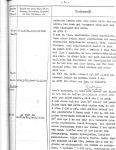
Photo 13. The U 123's War Diary, 12th January 1942, the entry describes the attack on the ship Cyclops [4]
With firing good data I launch a wet-heater torpedo from tube III. Angle on the bow 85° and target speed 9 knots. Aimed at the leading edge of the funnel, but the electrical firing system failed and the shot was fired manually 3 seconds later. Hit after 96 seconds behind the funnel.
During this attack on the British steam merchant Cyclops, due to malfunction of the electrical firing system, the torpedo was launched manually, in response to lighting the control lamp up, or in response to the voice command (in this case, the procedure that failed during first attack of U 109, succeeded).
U 123's attack, 23 March 1942 (grid CB 8172)
Es ist ein ganz moderner Motortanker mit kurzen Masten u. niedrigem, dicken Schornstein. Änlich “Norness” u. ich schätzte ihn auf 9500 brt. Auf eine e = 500 – 600 m schiesse ich einen Bug ato, Tiefe 3 m, vg = 10,5 sm, Lage 70°, Da der Horchraum meldet: Torpedo läuft, drehe ich hart ab nach St.B. Fehlschuss war auf die geringe E unmöglich. Es erfolgt nichts. Da meldet der Bugraum: Rohrläufer! Durch B.Ü. Fehler war es untergeschnitten, denn sonst hätte ich bei Lage 80° oder 90° noch einen 2. Aal schiessen können, der fertig war. Ich drehe nun hart weiter, um einen ebenfalls fertigen Heckaal zu schiessen. Da ich jedoch nun auf etwa 300 m breit zum Tanker lag, hatte er mich endlich doch gesehen und drehte hart ab nach St.B., Lage 180°. Befehle: Halt, sichern. Nach einiger Zeit wird gemeldet, dass Rohr V. Schuss gefallen ist. Der Gast hatte selbständig von Hand losgemacht, weil er auf das „Los“ wartete und glaubte es im Sprachrohr gehört zu haben. Auf den Befehlsgeber hatte er nicht geachtet. Der Aal sauste also irgendwohin in die Gegend. Der Rohrläufer war ¼ m im Rohr vorgerutscht und wurde dann mit Minenausstoss ausgestossen.

Photo 14. The U 123's War Diary, the entry describes the attack on 23rd March 1942 [5]
It is a very modern motor tanker with short masts and a low big funnel. Similar to "Norness" and I estimate about 9500 GRT. From a distance of 500 to 600 meters I fire one wet-heater torpedo from the bow tube, running depth 3 meters, target speed 10.5 knots, angle on the bow 70°. When the hydrophone operator reported that the torpedo was running I turned hard to starboard. A miss was not possible from this close distance. Nothing happened. Report from bow torpedo room: tube runner! Due to a misunderstanding the boat had already turned too far to fire a prepared second torpedo on angle on the bow 80° or 90°. I continue the hard turn to fire an also prepared stern torpedo. I was now showing my broadside to the tanker from a distance of 300 meters, so he finally saw me and turned away to starboard, angle on the bow 180°. Ordered: stop attack and secure the tubes. After some time it is reported that the torpedo was fired from tube V. The crewman had fired it manually on his own because he was waiting for the order to fire and believed he heard it in the voice tube. He did not look at the torpedo order telegraph. The torpedo was heading to anywhere. The tube runner had moved ¼ m in the tube and was jettisoned with the mine discharge gear.
During this attack an unintentional torpedo launch from the aft tube occurred. It was result of misunderstanding while passing orders. The torpedo tube operator who waited for the order to launch, did not hear the order to secure the tubes. When he heard through the voice tube the order similar to "Los!", he manually launched the torpedo. One can note the reference to the torpedo order telegraph which was installed on some early-war U-Boats.
U 123's attack, 2 April 1942 (grid DC 1196)
Schuss Rohr VI. bei Lage 100°. Da die vg mir doch noch geringer schien, kam ich achterer Mast ab. Da viel auch noch die elektrische Abfeuerung aus und der Schuss fiel 3 sec zu spät von Hand. Die Visierlinie zeigte auf den Schornstein. Da es ein grosser Winkel war hatte ich sofort das Gefühl eines Fehlschusses und befehl auf Artilleriegefechtsstationen. Der Aal steuerte jedoch richtig den Winkel ein und nach 40 sec meldete der Horcher, dass Torpedogeräusch ausgesetzt hat, ohne Aufschlag zu hören. Es war genau die Schussentfernung. Die Schussauswertung ergab, dass der Aal hätte treffen müss. Es war der Tanker „Liebre“ von 7057 Brt, der nach Gröner 10 sm läuft. Alle Fehler, wie falsche vg, Lage kann stumpfer gewesen sein und Parallaxfehler durch falsche E ergeben eine Treffpunktsverlegung nach vorne. Bei dem achteren abkommpunkt und der Abfeuerungsverzögerung hätte es sich also günstig auswirken müssen. Da der Horcher bei den übrigen Fehlschüssen die Torpedos bis zum Ende der Laufstrecke horchte, hier aber nach 40 sec nichts mehr, vermute ich, dass der Tanker ein Netz gehabt haben muss.
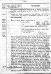
Photo 15. The U 123's War Diary, the entry describes the attack on 2nd April 1942 [5]
Fired torpedo from tube VI on angle on the bow 100°. It seemed to me that the target speed was even slower I aimed for the aft mast. But then the electrical firing mechanism failed too and the torpedo was launched 3 seconds later manually. The line of the sight was at the funnel. Because it was a big angle right away I felt it would miss and ordered the men to prepare an artillery attack. However the torpedo steered the correct angle and after 40 seconds the man at the hydrophone reported that the sound of the torpedo stopped without an impact being heard. It was exactly at the firing distance. An analysis showed that the torpedo would have hit. According to Gröner it is the tanker "Libre" (7057 GRT) which is running 10 knots. All the mistakes, like the wrong target speed, the angle on the bow which should have been more obtuse and the parallax error from an incorrect distance estimate would shift the impact point more ahead. The aiming point aft and the delay on firing would have had a favorable effect for us. Because the man at the hydrophone could hear the torpedoes of the other misses until the end of their run but in this case heard nothing after 40 seconds, I assumed that the tanker is equipped with nets.
In case of this attack, due to malfunction electrical firing system, the torpedo was launched manually with 3 seconds of delay. According to Kptlt. Hardegen, the torpedo should hit the target (whose speed was overestimated initially, but change of the aiming point in the last moment and delayed launch of torpedo had to compensate this error), however tanker was fitted with torpedo nets.
U 172's attack on not escorted, British steamer Fort Chilcotin, 24 July 1943 (grid FB 1517)
Fangschuß Rohr I: G 7a, vt = 40, Tiefe = 5, E = 1000 m.
Fehlschuß in-folge Ausfalls der Seitenübertagung Standsehrohr-Vorhaltrechner, die kurz vorher noch kontrolliert war. Schuß fiel infolgedessen mit falschem Schußwinkel.

Photo 16. The U 172's War Diary, 24th July 1943, the entry describes the attack on the ship Fort Chilcotin [6]
Coup de grâce from tube I: wet-heater torpedo, angle on the bow 40°, running depth 5 meters, distance 1,000 meters.
Miss due to the failure of bearing transmission from the attack periscope to the torpedo calculator, which had been checked shortly before. Because of this wrong gyro angle.
This torpedo attack (on British steam merchant Fort Chilcotin which detached from the convoy JT-2) failed due to undetected malfunction of the target bearing transmission system. The torpedo calculator received incorrect target bearing and, as a result, wrong gyro angle was calculated.
U 482's on convoy HX-305, 8 September 1944 (grid AM 5387)
Im Boot wird mit blossem Ohr starkes Rauschen gehört, genau wie am 2.9. als der Geleitzug überlief.
Mehrere Horchpeilungen achteraus und in 30, 50, 80 Grad, Dampfergeräusche.
Auf Gefechtsstationen, Auf Sehrohrtiefe.
Im Angriffssehrohr nur eben Schattenmassen auszumachen. Übergangen auf Zentralsehrohr. Hier ist Helligkeit für Unterwasserangriff, ausreichend. Boot steht tatsächlich wieder mitten in Einlaufgeleit, auf gleichen Kurse mitlaufend die nächststehenden Dampfer sind gut auszumachen ein Gesamtüberblick über Formation und Stärke Geleit jedoch nicht zu gewinnen.
Schuss aus Rohr III (Ato) auf Frachter 5000 BRT
Schussunterlagen: Tiefe 6, Torpedogeschw. 40,
Vg. 8, Lage rechts 110 E. -8,
Abkommpunkt Mitte, Pi I
Treffer 0 min. 42 sec. Treffer nicht beobachtet.
Schuss aus Rohr I (T 3) auf Frachter 5000 BRT.
Schussunterlagen: Tiefe 6, Vg 8, Lage links 120,
E.-8 Abkommen Mitte, MZ ein.
Fehlschuss da am Vorhaltrechner noch Torp. Geschw. 40 eingestellt war. Fehler von mir, da bei Wertegeben vergessen.

Photo 17. The U 482's War Diary, 8th September 1944, the entry describes the attack on the convoy HX-305 [7]
A loud rushing is heard with the naked ear in the boat, exactly as on 2 September when the convoy overran.
Several sound bearings astern and in 30°, 50°, 80°, steamer sounds.
To Action stations, to periscope depth.
In the attack periscope only smooth shadow masses are distinguished. Switched over to the control room periscope. Here it is bright enough for a submerged attack. In fact the boat is again in the middle of an inbound convoy, ran along on the same course, the nearest steamers are easily distinguished, but failed to gain an overall view of the formation and strength of the convoy.
Shot from tube III (wet-heater torpedo) on freighter 5000 GRT
Firing data: torpedo running depth 6 meters, torpedo speed 40 knots
target speed 8 knots, angle on the bow 110, bow right, distance 800 m
aim point center, pistol type: Pi 1
Hit after 42 seconds, no effect observed
Shot from tube I (electric torpedo) on freighter 5000 GRT
Firing data: torpedo running depth 6, target speed 8, angle on the bow 120, bow left
distance 800 meters, aim point center, influence pistol
Miss because the torpedo speed still set to 40 knots at the torpedo calculator. Error by me, because I forgot to specify the value.
During this attack first (wet-heater) torpedo was launched with the speed of 40 knots. The same value of torpedo speed was also set at torpedo calculator. Because the hit was not observed, it was decided to launch second torpedo. This torpedo was electrically driven and could run with speed 30 knots only. However, it was forgotten to update the torpedo speed at torpedo calculator, so calculated value of deflection angle was to small (β ≈ 10° instead of ≈ 13°) and torpedo passed behind the target.
U 518's attack on not escorted, Brazilian motor merchant Brasiloide, 18 February 1943 (grid FJ 8524)
10.02.43
In der Torpedofeuerleitanlage ist die Seitenübertragung vom UZO zum Tvhre endgültig ausgefallen, die schon seit Tagen andauernden Versuche, die Störungen zu beheben, blieben erfolglos.
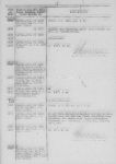
Photo 18. The U 518's War Diary, 10th February 1943, the entry describes the malfunction of the torpedo fire control system [8]
The part of the torpedo fire control system responsible for transmitting the target bearing from UZO night sight to the torpedo calculator has failed permanently, for days ongoing attempts to repair the malfunction have been unsuccessful.
18.02.43
Angelaufen zum Buganlauf. Wegen Ausfall der Seitenübertragung vom UZO zum Tvhre muß mit fester Seite geschoseen werden.
[…]
Zweierfächer aus Rohr I u. IV.
Feste Seite 0, Vg. 12, Gamma links 80, E 3000, Tiefe 2.

Photo 19. The U 518's War Diary, 18th February 1943, the entry describes the attack on the ship Brasiloide [8]
Photo 20. The U 518's War Diary, 18th February 1943, the entry describes the attack on the ship Brasiloide [8]
Ran in for an attack with bow tubes. Due to failure of the target bearing transmitting system must shoot with fixed target bearing.
[…]
Two-torpedo salvo from tubes I and IV.
Fixed target bearing 0, target speed 12, angle on the bow 80, bow left, distance 3000, torpedo running depth 2.
Due to malfunction of the target bearing transmission system between UZO night sight and torpedo calculator, during the attack (on Brazilian motor merchant Brasiloide) the procedure described in chapter II A (Feste Seite) – attack with the fixed target bearing equal to 0, was used. Target data and fixed target bearing equal to 0 were set at the torpedo calculator. The calculated gyro angle was set at torpedoes. The torpedoes were launched when target appeared in the sight (which was set at bearing 0) graticule.
U 615's attack on non escorted, British motor merchant Empire Star, 23 October 1942 (grid BD 3984)
rw. 20° Dampfer, Bug rechts 0-5° Abstand 8 sm, kommt schnell näher
getaucht zum Angriff
rw. 30° Bug rechts 20° 6 sm ab, Gegner steuert S, Fahrt 12-14 sm
Fueuerleitanlage ausgefallen
Entschluß: 4er Fächer auf wertvollen Dampfer
Schuß mit fester Seite
4er Fächer mit feseter Seite
Nach 61 sec. Heller metall. Schlag im ganzen Boot gehört, vermutl. Pi-Versager. Nach 67 sec
Treffer Heck, nach 20 sec weitere Explosion.
Gegner ist Schiff der “Sydney-Star” Klasse.
[…]
Fangschuß aus Rohr V mit festem Schußwinkel, Fehl, da durch BÜ-Fehler 20° falsche Einstellung.

Photo 21. The U 615's War Diary, 23rd October 1942, the entry describes the attack on the ship Empire Star [9]
Steamer true bearing 20°, angle on the bow 0-5°, bow right, distance 8 nm, comes quickly closer, dived to attack.
True bearing 30°, angle on the bow 20°, bow right, 6 nm away, target steers southerly course, speed 12-14 knots.
Torpedo fire control system fails.
Decision: 4-torpedo salvo on a valuable steamer.
Will shoot with fixed target bearing.
4-torpedo salvo with fixed target bearing
After 61 seconds a bright metallic impact heard in the entire boat, suspect a impact pistol failure. After 67 seconds hit aft, after 20 seconds another explosion in the ship.
Target is the "Sydney-Star" class.
[…]
Coup de grace from tube V with fixed target bearing, missed because of an order transmitting failure 20° incorrect setting.
During the attack on British motor merchant Empire Star it was found that the torpedo fire control system is out-of-order. Therefore, the procedure described in the chapter II A (Feste Seite), attack with fixed target bearing, was used. This suggests, that target bearing transmission system between periscope and torpedo calculator failed. The final shot (Coup de grace) missed the target, because the incorrect value 20° was set at torpedo calculator (most likely incorrect target bearing was set manually).
References:
[1] The War Diary for U 48's 6th patrol
[2] The War Diary for U 69's 3rd patrol
[3] The War Diary for U 109's 4th patrol
[4] The War Diary for U 123's 7th patrol
[5] The War Diary for U 123's 8th patrol
[6] The War Diary for U 172's 5th patrol
[7] The War Diary for U 482's 1st patrol
[8] The War Diary for U 518's 2nd patrol
[9] The War Diary for U 615's 1st patrol
In the mid 20's of the twentieth century, some manufacturers of the optical equipment (Zeiss, Nedinsco, Barr & Stroud, Kollmorgen) offered periscopes fitted with feature called Stabilized Azimuth Line (Germ. Feste Linie im Raum). In the field of view of such periscope, the vertical line was visible whose position in space was fixed (stabilized by gyro-repeater). In other words, despite the changes of the U-Boat course and related changes of the field of view, the vertical azimuth line was still in the same place (at the same true bearing, relative to the true north).
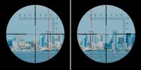
Drawing 1. The position of the stabilized azimuth line before and after course change by a few degrees to starboard
The vertical line made possible to measure the target speed accurately (knowing its length), regardless its course (or the angle on the bow actually). To get the target speed, the time interval between passing the vertical line by target bow and target stern was measured. Then, target length (in meters) was divided by time interval (in sec), giving the target speed (in m/sec). To get (approximate) speed in knots, the result should be multiplied by 2.
To make the calculation easier, the dedicated circular slide rules were manufactured, so the result could be get immediately.

Drawing 2. German circular slide rule (vg-Scheibe) manufactured by Dennert & Pape company [1]
What is important is the fact that the result is irrespective of the angle on the bow (does not depend on the position of the observer relative to the target).
The largest limitation of this method was the influence of the own motion on the result of measurements. The most accurate results were achieved, when own boat was stationary. When own boat was moving, the result depended on the own speed and the target bearing.
The own speed influenced the result slightly only when the target bearing was 0 or 180° and own course was perpendicular to the target course (i.e. the own velocity's component, which is parallel to the target velocity, is equal to 0). The largest influence of the own speed was in case, when target was abeam and own course was parallel to the target course (i.e. the own velocity's component, which is parallel to the target velocity, was the largest, equal to own speed). In the extreme case, when own and target course are parallel and own speed is equal to the target speed, the speed measured by means of this method would be equal to 0.
The other limitation of this method is relatively long time required to measure time and thus a long time of exposure of the periscope head over the water surface (this increased the possibility of spotting). I.e. when measuring the speed of the Admiral Hipper heavy-cruiser (length 212 m) cruising with speed 19 knots, it would take 23 seconds to take the measurement.
The author did not find information about implementation of the stabilized azimuth line component in the German periscopes manufactured by Zeiss company, however based on the manual (dating from 1940) of the American Type 2 periscope (manufactured by Kollmorgen company, type 89KA40/1.414), one can present the general operating principle.

Drawing 3. The stabilized azimuth line component in the American Type 2 periscope manufactured by Kollmorgen company [2]
In the lower part of the ocular box the selsyn receiver (gyro repeater) was located. By means of the set of gears, it moved the gear rack to the one side or another. This gear rack was attached to the lower end of the pointer lever. To the upper end of this lever, the pointer was attached. This pointer was visible in the periscope field of view as a stabilized azimuth line.
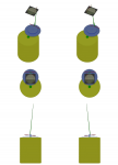
Drawing 4. The operating principle of the stabilized azimuth line component in the American Type 2 manufactured by Kollmorgen company
The shaft of the gyro-repeater rotated when the submarine changed her course. The rotation of the shaft was transmitted (by means of the set of gears) at the gear rack which changed the inclination of the pointer lever. As the pointer lever inclination changed, the pointer (visible as the stabilized azimuth line) moved across the periscope field of view to the left or right, to keep the fixed position in space despite the course change.
Regarding the Zeiss periscopes, in the Zeiss Archiv only the following description could be found:
Die Feste Linie im Raum ist eine Zusatzeinrichtung in U-Boot-Sehrohren. Sie dient dazu, die Geschwindigkeit eines Gegnerschiffes aus seiner bekannten oder geschätzten Länge zu ermitteln. Im Gesichtsfeld des Sehrohres erscheint ein senkrechter Faden, der durch den Tochtermotor einer Kreiselkompaß-Mutteranlage raumfest gesteuert wird und daher von Kursänderungen und Kursschwankungen des U-Bootes unbeeinflußt ist, wenn am Sehrohr 6fache Vergrößerung eingestellt ist. Der Faden stellt also eine feste Richtung im Raum dar. Die Bewegung des senkrechten Fadens ist begrenzt und entspricht einem Gesichtswinkel von +/- 3 ½°. Wird der Kurs des U-Bootes bei eingeschaltetem Tochtermotor um mehr als +/- 3½° geändert, so läuft der Faden gegen einen Anschlag und bleibt seitlich im Gesichtsfeld stehen. Der Motor arbeitet über eine Rutschkupplung und läuft dabei ohne Schaden weiter. Mit einem Einstellhebel kann der senkrechte Faden in jede beliebige Lage innerhalb des Beeiches von +/- 3½° gebracht werden. Nach Loslassen des Einstellhebels geht dieser selbsttätig in die Mittellage zurück und der senkrechte Faden erhält seine volle Bewegungsfreiheit wieder und wird vom Tochtermotor gesteuert. Die Bestimmung der Zielgeschwindigkeit wird wie folgt ermittelt: Mit einer Stoppuhr wird die Zeit gemessen, die ein Gegnerschiff von bekannter oder geschätzter Länge braucht, um die Feste Linie im Raum zu passieren. Aus dieser Stoppzeit lässt sich die Geschwindigkeit des Gegnerschiffes errechnen, wobei noch der eigene Kurs, die eigene Geschwindigkeit und der Kurs des Gegnerschiffes zu berücksichtigen sind.
The stabilized azimuth line component is an additional equipment of the U-Boats' periscopes. It is used to determine target speed based on known or estimated target's length. In the periscope field of view (when switched to high power mode, i.e. 6x) the vertical line is visible which position is controlled by gyro-repeater. The gyro-repeater controls position of the vertical line to keep it fixed in the space. The horizontal movement of the vertical line is limited to +/- 3 ½°. If the U-Boat course (with gyro-repeater enabled) changes more than +/- 3 ½°, the horizontal movement of the line will be limited by the limit stop at the border of the field of view. The gyro-repeater is coupled with the gear controlling the vertical line position by means of the friction clutch, therefore, when the vertical line is locked at the border of the field view, the gear will not be damaged. By means of the adjusting lever, the vertical line can be moved to any position limited to +/- 3 ½°. When the adjusting lever is released, the position of the vertical line is controlled by gyro-repeater again. The target speed is determined in the following way: by means of the stop-watch, the time required to pass the vertical line by the target (of known or estimated length) is measured. Based on this time one can calculate the target speed. The result is irrespective of the own course and speed and target course.
One should note that azimuth line is stabilized relative to the course changes only, and not relative to the periscope bearing changes.

Drawing 5. The position of the stabilized azimuth line before and after rotation of the periscope by a few degrees to right
In other words, slight changes of the own course (caused by yaw or helmsman inaccuracy), particularly visible when switched to the high power mode (6x), were compensated by component of the stabilized azimuth line (Uncompensated movement of the line by 1° in case of target cruising 1000 m away resulted in the linear movement by 17 meters. In case of the Admiral Hipper heavy-cruiser, the measurement error would be 8%). The intentional course changes were also compensated, up to 32° (when switched to the low power mode, 1,5x) or 8° (when switched to the high power mode, 6,0x).
Since the component of the stabilized azimuth line was internal part of the ocular box, when the periscope was rotated, the stabilized azimuth line rotated as well.
The two restrictions presented above (the dependence of the result accuracy on the own speed value and target bearing, the long time of the periscope head exposure) caused (most likely) that periscopes fitted with component of the stabilized azimuth line were not used on German U-Boats and American submarines.
There is evidence that periscopes fitted with component of the stabilized azimuth line manufactured by Zeiss company were to be installed on new Polish submarines (type Orzeł), ordered in France at the end of 1938.
In case of German U-Boats, the vestige of the Feste Linie im Raum method is visible in the navy regulations (Marine Dienstvorschriften) as well as in the U-Boats equipment (more specifically in the construction of the type StaS C/2 attack periscope).
In the regulations Torpedo-Schießvorschrift, Heft II, Ermittlung der Schußwerte dating from 1930 (i.e. from the period of Reichsmarine, with no U-Boats in service), in the chapter describing the methods of speed measurements, there is a paragraph:
Für das Schätzen der Gegnerfahrt gibt das Aussehen der Bug- und Hecksee, das Auswehen des Schornsteinrauchs (unter Berücksichtigung von Richtung und Stärke von Seegang und Wind), gegebenenfalls die Auswanderung gegen einen festen Punkt, die Auswanderung der Peilung (unter Berücksichtigung der eigenen Fortbewegung) Anhaltspunkte.
To estimate the target speed the following can be used: the appearance of the bow wave and wake, the deflection of the smoke from stacks (taking into account direction and force of the wind and sea state), finally, one can measure the time needed by target to pass through the fixed point or measure rate of change of the target bearing (taking into account the own speed).
In the regulations Torpedo-Schießvorschrift, Heft 2, Schießverfahren dating from 1938 (i.e. from the period of Kriegsmarine, with 45 U-Boats in service), in the chapter describing the methods of speed measurements, there is a paragraph:
Für das Schätzen der Gegnerfahrt gibt das Aussehen der Bug- und Hecksee, lediglich einen Anhalt, maßgebend darf nur die Auswanderung der Peilung unter Berücksichtigung der eigenen Fahrt, der Lage und Entfernung sen.
Ein gutes Hilfsmittel zur Kontrolle der Schätzung der Gegnerfahrt ist bei bekannter Gegnerlänge das Durchwandernlassen des Gegners durch einen festen Punkt, z.B. eine Landmarke oder durch einen rechtweisenden Peilstrahl. Unabhängig von Lage und Entfernung ist die Zeit, ein Schiff zum Durchlaufen eines im Raume festliegenden Peilstrahls gebraucht, ein Maß für seine Geschwindigkeit. Hierzu wird die Zeit vom Einlaufen des Bugs in den Visierfaden bis zum Verlassen des Hecks gemessen.
Es ist: vg = (Gegnerlänge in m) / (Zeit in sec) * 2 (sm/h)
Voraussetzung für die Bestimmung ist, daß der Angreifer gestoppt liegt oder den Gegner zu Beginn der Messung recht vorausnimmt und diesen Kurs durchhält. Die als Anlage 4 beigefügte Tabelle ermöglicht es, aus der abgestoppten Zeit, bei bekannter Länge des Gegners, die Gegnerfahrt zu bestimmen.
Beispiel: Ist die abgestoppte Zeit, die ein Schiff zum Durchlaufen der Peilung gebraucht, 15 sec und seine Länge 180 m,
so ist: vg =180 * 2 / 15 = 24 sm/h
To estimate the target speed, one can observe the appearance of the bow wave and wake. To get the accurate speed value, the rate of change of the target bearing method should be used (taking into account the own speed, the angle on the bow and distance).
To verify the estimated target speed (knowing target's length), one can measure the time needed by target to pass through the fixed point, eg. terrain object at the shore or vertical line of the periscope graticule. Irrespective of the angle on the bow and distance, the time needed to pass through the fixed point can be used to calculate target speed.
We get: vg = (target length in meters) / (time in seconds) * 2 (knots)
It is required that own boat is not moving or the target is at the 0 bearing in the moment of measuring the time. The Appendix 4 contains the table which can help calculate the target speed (of known length) based on the measured time.
Example: target of length 180 meters passed through the fixed point in space in 15 seconds,
so: vg =180 * 2 / 15 = 24 knots.
In the regulations M.Dv. 416 Torpedo-Schießvorschrift für U-Boote dating from 1943 there is a table Bestimmung der Gegnergeschwindigkeit aus bekannter Ziellänge und Zeit des Durchwanderns durch einen feststehenden Punkt bzw. feste Linie im Raum, which helps determining the target speed (in knots) based on its length and time needed to pass through the stabilized azimuth line.

Drawing 6. The table that helps determining the target speed based on its length and time needed to pass through the stabilized azimuth line [3]
The type StaS C/2 attack periscope was not fitted with the component of the stabilized azimuth line in the strict sense, however it was equipped with the gear for reading the true bearing. This gear, which shows the true bearing (relative to the north) with 20' accuracy, could be used as a stabilized azimuth line component.

Photo 1. The type StaS C/2 periscope with the gear showing the true bearing visible [4]
The procedure was as follows: the periscope was set in such way, that one of the vertical lines of graticule was in the front of the target bow. Then the time interval between passing the target bow and target stern through this line was measured. In the same time, the other person (not one looking through the periscope) observed the true bearing counter and, if required, by means of the hand-wheel trained the periscope to keep the same value (i.e. true bearing) when the boat changed course (due to yaw or intentional course change).

Photo 2. Type StaS C/2 periscope with hand-wheel for training (1) and true bearing counter (2) [5]
References:
[1] Thomas Müller, Analogrechner auf deutschen U-Booten des Zweiten Weltkrieges
[2] Submarine Periscope Type 2, 1940
[3] Tabellenheft zur Torpedo-Schießvorschrift für U-Boote, 1940
[4] Photographs taken during inspection by U.S. Naval Officers - Enclosure C of ONI Report
[5] Fritz Köhl, Axel Niestle, Vom Original Zum Modell - U-Boot Typ VIIC
"The Boat", the most known movie about German U-Boats, presents two torpedo attacks (actually one attempt of the submerged attack on a destroyer and night surface attack on a convoy). In both cases, the torpedo calculator is visible on the movie screen, for a while. Due to the subject of this website, this article contains some comments related to the torpedo attacks, which were presented in the movie and described in the novel (the basis for the movie).
The attack on a destroyer.
The presented movie fragment shows the interrupted attack on a destroyer. The sequence of the orders and acknowledgments issued during the preparation for the attack can be compared with torpedo launching procedures.
A short comment for the torpedo calculator, that was presented in the movie. It seems, it is an accurate replica of the device from U 995, which is displayed in the Marine-Ehrenmal in Laboe. Because the movie was produced at the turn of the decade 70/80, the filmmakers could see the calculator in its original form (because U 995 serves as an museum-ship only since 1972). Now, after almost 40 years on display and several renovations, the calculator lost its original appearance (mainly dials and labels).
In the movie, the replica of the device from U 995 (that is the late-war version) was used, therefore there is a historical inaccuracy: the calculator is fitted with angle of impact control lamp, which in fact appeared in the end of 1942, while the movie presents the 7th patrol of U 96, which took place from 27 October to 6 December 1941.
For comparison with the movie, the respective novel fragment is quoted below (in German), with dialogues in bold letters.
Kaum haben wir uns um die Back zurechtgesetzt – der Leitende, der II LI und ich –, als Gebrüll aus der Zentrale dringt. Der Leitende geht sofort in eine lauernde Stellung. Eine Meldung von der Brücke wird durchgegeben: »Mastspitze backbord voraus!« Noch ehe ich richtig zu denken beginne, bin ich schon im Gang zur Zentrale: der Geleitzug! Vor dem Leitenden entere ich auf. Der Regen ist heftiger geworden. Mein Pullover wird von Spritzwasser und Regen sofort durch näßt. Bei all der Hast habe ich vergessen, meine Öljacke vom Haken zu langen. Ich höre den Kommandanten: »Hart steuerbord auf hundertachtzig Grad gehen!« Ein Brückenposten reicht mir unaufgefordert sein Glas. Ich suche in der Blickrichtung des Kommandanten. In den Okularen erscheint das Grau einer Regenfahne. Nichts als trübes Grau! Mit angehaltenem Atem zwinge ich mich zur Ruhe, suche das rechte Ende der Regenfahne und führe dann das Glas von rechts nach links ganz langsam über sie hin. Da entdecke ich in dem gestreiften Grau einen haardünnen Strich, der so gleich wieder verschwindet. Wars eine Täuschung? Bilde ich mir den Strich nur ein? Ich atme tief, mache mich in den Kniegelenken locker, federe leicht durch, lasse das Glas auf den Fingerspitzen aufsitzen. Das Boot dreht unter mir. Ich finde die Richtung nicht gleich, orientiere mich wieder am Kommandanten. Da ist der Strich wieder! Er zittert und tanzt im Glas hin und her. Ein Mast! Ohne Zweifel. Aber: ein Mast und keine Rauchfahne dicht dabei? Nur dieser einzelne haardünne Mast? So scharf ich auch meinen Blick mache, ich finde nichts als diesen Mast, der sich langsam höher über die Kimm herauszuschieben scheint. Ich weiß: Jeder Dampfer hat eine Rauchfahne, die ihn längst verrät, ehe seine Masten hinter der Kimm hochkommen. Das da kann also kein Dampfer sein. Verdammt noch mal – wo ist der Strich jetzt? Da habe ich ihn wieder. Man müßte ihn jetzt schon mit bloßen Augen sehen können. Ich setze das Glas ab und suche – da ist er schon! Der Kommandant hat die Lippen zwischen die Zähne gezogen: Wieder führt er das Glas an die Augen. Als spräche er für sich, stößt er zwischen den Zähnen hervor: »Scheißzerstörer!« Eine Minute vergeht. Mein Blick saugt sich an dem dünnen Strich über der Kimm fest. Erregung pocht mir hoch im Hals. Es gibt jetzt keinen Zweifel mehr: Der Mast kommt höher heraus – der Zerstörer hält also direkt auf uns zu. Mit unseren langsamen Maschinen haben wir keine Chance mehr, über Wasser davon zukommen. »Die müssen uns gesehen haben! Verdammt – verdammt!« flucht der Kommandant und gibt mit nur wenig erhobener Stimme Alarm. Mit einem einzigen Satz bin ich am Turmluk. Knallendschlagen meine Stiefel auf den Flurplatten auf. Der Kommandant steigt als letzter ein. Er wirft das Luk dicht. Noch ehe er es ganz festgezogen hat, befiehlt er: »Fluten!« Der Kommandant bleibt im Turm. Mit gleichmäßiger Stimme gibt er von oben in die Zentrale herab: »Auf Sehrohrtiefe einsteuern!« Der Leitende fängt das Boot ab. Der Zeiger des Tiefenmanometers bleibt stehen, dann streicht er langsam über die Skala zurück. Dufte steht in nassem Ölzeugschwer atmend neben mir. Zeitler und Böckstiegel haben sichvor die Druckknöpfe der Tiefensteuerung gehockt. Ihr Blickhängt an der Wassersäule im Papenberg. Der I WO läßt mitgesenktem Kopf Regenwasser von der Krempe seines Südwesters abtriefen. Keiner sagt ein Wort. Nur ganz leise, wie von gepolsterten Türen gedämpft, klingt das Summender elektrischen Maschinen von achtern. Endlich fällt von oben die Stimme des Kommandanten in die Stille: »Frage Tiefe?« »Zwanzig Meter!« meldet der Leitende. Die Wassersäule im Papenberg sinkt langsam ab: Das Boot steigt. Gleich kommt das Objektiv des Sehrohrs frei. Da das Boot noch nicht auf ebenem Kiel liegt, läßt der Leitende aus dem vorderen Trimmtank nach achtern trimmen. Langsam richtet sich das Boot in die Waagerechte ein. Es liegt aber nicht ruhig. Die Seen bewegen es nach allen Richtungen.Sie saugen, ziehen, schieben. Da wird die Sehrohrbeobachtung verdammt schwierig werden.Ich lausche nach oben, warte auf die Stimme des Kommandanten, da meldet der Horcher: »Steuerbord querabein Zerstörer!« Ich gebe die Meldung nach oben weiter. »Genehmigt«, antwortet- der Kommandant. Dann, genauso trocken: »Auf Gefechtsstationen!« Der Horcher beugt sich mit dem Oberkörper aus dem Horchschapp in den Gang heraus. Seine blicklosen Augen sind geweitet. In der frontalen Beleuchtung ist sein Gesicht eine flächige Maske, die Nase nur zwei Löcher. Der Horcher ist nun, neben dem Kommandanten, der einzige, dessen Sinne aus der Stahlröhre nach außen dringen. Der Kommandant sieht den Gegner, der Horcher hört ihn. Wir anderen sind blind und taub. Jetzt meldet der Horcher: »Horchpeilung wird stärker – wandert leicht nach achternaus!« Die Stimme des Kommandanten klingt gedrosselt: »Rohr eins bis vier bewässern!« Dachte ich mir doch: Der Alte will den Zerstörer annehmen. Der ist auf einen roten Wimpel scharf. Ein Zerstörer fehlt nochin seiner Sammlung. Als nach dem Alarmbefehl »Auf Sehrohrtiefe einsteuern!« kam, wußte ich schon Bescheid. Von oben wieder die Stimme des Kommandanten: »An Zentrale – LI – genau auf Tiefe halten!« Wie soll er nur, sage ich mir, bei diesem schiebendem Seegang? Die dünnen Muskeln im Gesicht des Leitenden straffen sich und entspannen sich wieder in schnellem Rhythmus. Es sieht aus, als ob er Kaugummi kaue. Wehe, wenn das Boot zu hoch kommt, wenn es die Oberfläche durchbricht und uns dem Gegner verrät! Der Kommandant hockt im schmalen Raum zwischen Sehrohr Schacht und Turmwand auf dem Sehrohrsattel, den Kopf gegen die Gummimuschel gedrückt, die breit gespreizten Schenkel gegen den mächtigen Schaft gepreßt. Die Füße hat er auf den Pedalen, mit deren Hilfe er die mächtige Säule mit samtseinem Sitz geräuschlos und schnell um den ganzen Gesichtskreis drehen kann, die rechte Hand hält er am Hebel,der den Motor zum Aus- und Einfahren des Rohres schaltet. Jetzt summt der Sehrohrmotor: Der Kommandant zieht das Sehrohr ein Stück ein. Er hält den Sehrohrkopf so dicht an der Oberfläche des Wassers, wie es nur geht.
Der Leitende steht vollkommen reglos hinter den zwei Mann der Brückenwache, die jetzt die Tiefensteuerung bedienen. Er hat den Blick auf den Papenberg geheftet, in dem die Wassersäule ganz langsam auf und ab steigt. Jedes Auf und Abbedeutet ein Steigen oder Sinken des Bootes.Kein lautes Wort. Das Summen des Sehrohrmotors klingt wie durch feine Filter passiert, der Motor springt an, stoppt, dann ertönt wieder das Summen. Der Kommandant fährt das Sehrohr nur für ganz kurze Augenblicke aus und läßt es gleich wieder vom Wasser überspülen. Der Zerstörer muß also ganznahe sein. »Rohr fünf bewässern«, kommt es geflüstert von oben. Der Befehl wird leise an den Hecktorpedoraum weiter geleitet. Wir sind mitten im Gefecht. Ich lasse mich in den Rahmen des Kugelschotts sinken. Von achtern kommt die geflüsterte Meldung: »Rohr fünf ist klar zum Unterwasserschuß bis auf Mündungsklappe.« Alle Rohre sind also bewässert. Alle fünf Torpedos schwimmen schon. Jetzt fehlen nur noch die Preßluftstöße, um sie auf Fahrt zu schicken, und vorher das Öffnen der Mündungsklappen. Der Kommandant will die Ruderlage wissen. Ich merke auf einmal, daß ich noch einen halben Bissen Brot im Mund habe. Brotbrei mit Hartwurstflomen. Schmeckt schon säuerlich. Ich habe das Empfinden, ich hätte irgendwo diese Situation schon erlebt. Bilder schimmern auf, schieben sich durcheinander, überlagern, durchdringen sich. Es ist, als ob durch ein kompliziertes System Gegenwarts eindrücke über das Gedächtniszentrum geleitet würden und von dort als Erinnerung ins Bewußtsein kämen. Der Alte ist verrückt – bei diesem Seegang einen Zerstörer anzugreifen!
Aber der Seegang hat auch wieder sein Gutes. Da ist unser Sehrohr kaum zu erkennen. Der Schaumstreifen, der es verraten könnte, ist unter dem anderen Gequirl schwer auszumachen. Das Tropfen in die Bilge klingt scharf, wie lautsprecher verstärkt. Ein Glück, daß bisher alles geklappt hat:keine Einsteuerungsschwierigkeiten. Der Leitende war gut präpariert, hatte alles gut durchgerechnet. Wenn der Alte schießen sollte, muß der Leitende gleichfluten, um das Gewicht der Torpedos auszugleichen. Sonst käme das Boot hoch. Dreißig Zentner wiegt ein Torpedo – also eintausendfünfhundert Liter fluten pro Torpedo. Multipliziert mit der Zahl der geschossenen Torpedos macht das eine Menge. Der Kommandant schweigt. Es ist sehr schwer, einen Zerstörer zu treffen. Geringer Tiefgang. Ändert zu schnell Kurs. Aber wenn ein Zerstörer getroffen wird, ist er gleich weg, wie fortgepustet. Die Torpedodetonation – der Geysir aus Wasser und Eisenfetzen – und dann nichts mehr zu sehen. Da kommt die feste Stimme des Kommandanten von oben: »Mündungsklappen öffnen. Schaltung Rohr eins und zwo! Gegnerfahrt fünfzehn. Bug links. Lage sechzig. Entfernung tausend!« Der II WO stellt die Werte auf der Rechenanlage ein. Aus dem Bugraum wird gemeldet, daß die Mündungsklappen geöffnet sind. Der I WO gibt leise, aber deutlich akzentuiert nach oben: »Rohr eins und zwo klar zum Unterwasserschuß!« Jetzt hat der Kommandant die Hand schon auf dem Abschußhebel und wartet, daß der Gegner ins Fadenkreuz einwandert. Sehen! Nur sehen können! Die Stille leistet der Phantasie Vorschub. Katastrophenbildertauchen auf: Ein Zerstörer, der zudreht bis in Lage Null. Ein Zerstörerbug, der mit schäumender Bugwelle – den weißen Knochen im Maul – hoch wächst und zum Rammstoß ansetzt. Aufgerissene Augen, der scharfe Riß eines Lecks, kantenzerfetzte Stahlbleche, grüne Wasserschwälle, die durch das Leck wie durch eine Düse fauchen.Da schlägt die Stimme des Kommandanten scharf wie ein Peitschenhieb von oben herunter: »Mündungsklappen schließen. Auf sechzig Meter gehen. Schnell auf Tiefe!«
Below, the page from U 96's War Diary, 1st November 1941, is shown. There is a record, which describes the attack of HMS Gorleston (gunboat being in escort of OS 10 convoy) on U 96. This event was the basis for a destroyer attack in the novel.
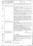
Photo 1. The record in the U 96's War Diary, 1st November 1941, describing the gunboat attack [1]
18:57 - Sighted by gunboat approaching from astern.
19:06 - Dived. Gunboat running at high speed, 220 RPM, makes small course changes. Attempting to shoot, at 500 meters range gunboat changes course towards us, probably sighted the periscope in the calm sea. Went to depth 70 meters.
During the approach observed gunboat signal: 1 flag 1 pennant, blue with white cross. In the masthead 3 men posted as a lookout.
19:50-20:16 - Several depth charge runs. 12 depth charges. Unusually poor pursuit. Sporadic low-pitch sonar impulses. I have the impression that from the start the gunboat had no sound location or sound bearings. The depth charges, in some cases only two per approach, were at the position of our submergence.
20:00 - On course 200 degrees.
Gunboat departs and surprisingly turns back on the dark horizon. It is still very light.
21:52 - Surfaced. Gunboat is visible at compass bearing 90 degrees at about 6000 meters. Ran off pre-flooded on electric motors on course 250 degrees.
The attack on a convoy.
The presented movie fragment shows the attack on a convoy. Also in this case, the sequence of the orders and acknowledgments can be compared with torpedo launching procedures
One more comment related to the torpedo calculator. At some point, the calculator operator reports "Deckung!" in response to turning off the angle of impact control lamp (which should not be present in this version of the calculator at all). Then the First Watch Officer issues the orders: "Lage laufend!", "Folgen!". These orders should be issued in reverse order (i.e. "Folgen!" first, which enables receiving the bearing value from the aiming device, followed by "Lage laufend!", when the process of automatic update of angle on the bow begins).
For comparison with the movie, the respective novel fragment is quoted below (in German), with dialogues in bold letters.
Der Kommandant weist den I WO an: »Anlaufen und gleich schießen. Nach dem Schuß sofort nach backbord drehen. Wenn jetzt die Wolke hochkommt, gehe ich ran!« Der I WO gibt die nötigen Befehle an die Rechenanlage, die mit einem Mann im Turm und einem zweiten in der Zentrale besetzt ist. »Rohr eins bis vier klar zum Überwasserschuß!« Jetzt werden alle vier Bugtorpedorohre geflutet. Vom Bugraum wird über Sprachrohr gemeldet: »Rohr eins bis vier klar zum Überwasserschuß!« »Schaltung UZO mit Vorhaltrechner. Abfeuerung Brücke!« befiehlt der I WO. Die Befehle kommen ihm glatt von den Lippen. Das kann er also. Das hat er gelernt. Der Maat an der Rechenanlage im Turm meldet die Ausführung der Befehle herauf. Der Alte tut, als gingen ihn die liturgischen Wechselgesängegar nichts an. Nur seine gespannte Haltung verrät, wie sehr er aufpaßt. Der I WO gibt jetzt an den Maat im Turm: »Gegnerlage Bugrechts – Lage fünfzig – Gegnerfahrt zehn Seemeilen – Abstand dreitausend Meter – Torpedogeschwindigkeit dreißig – Tiefe drei – Lage laufend.« Um den richtigen Vorhaltwinkel für die Torpedos braucht sich der I WO nicht zu kümmern. Den findet die Torpedorechenanlage. Die Rechenanlage hat direkte Verbindung mit dem Kreiselkompaß und der Zielsäule und ist außerdem direkt auf die Torpedos geschaltet, deren Schwenkmechanismus sie jetzt laufend beeinflußt: Jede Kursänderung des Bootes wird automatisch als Kurskorrektur auf die Torpedos übertragen. Der I WO braucht nur noch das Ziel im Fadenkreuz des Glases auf dem UZO zu halten. Der I WO beugt sich über die Optik: »Klar zum Seiten-vergleich! … Seite … Null!« »Der Anlauf muß gelingen«, murmelt der Kommandant. Wieder richtet er seinen Blick gegen den Mond. Die zweite Wolke ist stehengeblieben wie ein Fesselballon, der die vorgesehene Höhe erreicht hat. Drei Daumensprünge unter dem Mond: Da hängt sie nun und rührt sich nicht mehr. »Eine einzige Schufterei!« Der Obersteuermann droht mit der geballten Faust nach oben, ein Gefühlsausbruch, der mich von einem so ruhigen Mann wie Kriechbaum überrascht. Doch mir bleibt keine Zeit, mich über den Obersteuermann zuwundern; der Kommandant wendet mit einem heftigen Ruck sein Gesicht aus dem Schein des Mondes und befiehlt: »Beide Maschinen äußerste Kraft voraus! Hart backbord! Anlauf beginnt! Mündungsklappen öffnen!« Von unten wird die Wiederholung der Befehle heraufge-brüllt. Schon beginnt der Bug über die Kimm zu streichen. Ersucht die Schatten. »Mittschiffs! – Recht so! – Weiter neunzig Grad steuern!« Nun rast das Boot genau auf die Schatten zu, die von Sekunde zu Sekunde größer werden. Die Pflugschar des Bugs schneidet in die glitzernde See und wirft leuchtende Wasserschollen zur Seite. Die Bugwelle steigt auf und blinkt von tausend Pailletten. Das Vorschiff schiebt sich hoch heraus. Sofort kommt Spritzwasser über. Die Diesel laufen Hochtouren. Das Schanzkleid zittert. »Ziel auffassen!« befiehlt der Kommandant. Der I WO hält sich über die Optik gebeugt. »Da, die zwei, die sich überlappen, die nehmen Sie. – Da, haben Sie? – links neben dem einzelnen Dampfer! Der großekriegt Doppelschuß, die anderen Einzelschüsse. Doppelschuß auf Vorkante Brücke und kurz vor achterem Mast losmachen!« Ich stehe dicht hinter dem Kommandanten, der seinen Kopf gegen die Schiffe hin vorgeschoben hält. »Rohr eins bis vier fertig!« Herzklopfen bis hoch in den Hals. Meine Gedanken laufen durcheinander: die brüllenden Motoren – die Schatten – die silberne See – der Mond! Dieses Lospreschen! Ich denke, wir sind ein U-Boot – wenn das nur gut geht! Der I WO hält das Ziel im Glas gefaßt. Sachlich und trocken kommt seine Stimme aus seinem nach unten gewandten Mund. Er verbessert ständig seine Werte. Schon hat er die rechte Hand am Abfeuerungshebel. »Schaltung Rohr eins und zwo – Lage fünfundsechzig – Lage laufend folgen!« »Frage Lage?« »Lage siebzig … Lage achtzig!« Dicht neben meinem Ohr höre ich den Kommandanten: »Rohr eins und zwo – Feuererlaubnis!« Sekunden danach befiehlt der I WO: »Rohr eins und zwei los!« Ich mache alle Sinne scharf: kein Knall – kein Ruck im Boot– nichts! Das Boot prescht weiter, noch näher an die Dampfer heran. Die merken nichts! – Die merken nichts! »Schaltung Rohr drei!« »Rohr drei – los!« »Backbord zehn!« befiehlt der Kommandant. Wieder streift der Bug suchend über die Kette der Schiffe hin. »Schaltung Rohr vier!« höre ich den I WO. Er wartet, bis das neue Ziel einwandert und befiehlt: »Rohr vier … los!« Dicht unter dem anvisierten Dampfer entdecke ich in diesem Moment ein langgestrecktes Schiff, einen Schatten, der nicht so dunkel ist wie die anderen – wahrscheinlich grau bemalt. »Hart backbord! Auf Heckrohr schaltung!« Das war die Stimme des Kommandanten. Das Boot legt sich im Drehenträge auf die Seite. Die Schatten ziehen nach steuerbord hinüber. Der Obersteuermann ruft: »Fahrzeug dreht zu!« Ich sehe, wie sich jetzt unser Heck auf die Schatten richtet. Ich sehe aber auch, wie das helle Schiff schmaler wird. Jetzt ist sogar der Saum seiner Bugwelle zu erkennen. »Rohr fünf – los! … Hart steuerbord!« brüllt der Kommandant. Das Boot hat kaum nach der anderen Seite abgedreht, da zuckt drüben ein orangeroter Blitz auf, einen Sekundenbruchteil darauf noch einer. Eine gewaltige Fauststaucht mich in die Knie. Scharfes Sausen dringt wie ein kalter Stahl in mich ein. »Die Schweine, die schießen! – ALARM!« brüllt der Alte.
Short comment to the following novel fragment: Der I WO beugt sich über die Optik: »Klar zum Seiten-vergleich! … Seite … Null!«
The torpedo launching procedures do not contain a sequence of the such orders, however they are not necessarily fictional. Because the UZO night sight had to be mounted at the top of the UZO column before each usage, after it was installed, one should make sure, that sight line is correctly transmitted to the torpedo calculator (i.e. there is no misalignment due to mechanical failure, installation mistake or any clearance). Therefore, the First Watch Officer set the sight to the 0 bearing (accordingly to the azimuth circle) and passed this value to the conning tower, where the calculator operator compared it with the value read from respective dial, which was transmitted by synchro link).
This procedure was unnecessary during submerged attack, because both periscopes were permanently coupled with target bearing transmitters.
Below, the page from U 96's War Diary, 31st October 1941, is shown. There is a record, which describes the attack on OS 10 convoy (which ended with sinking the ship Bennekom) and a counterattack of the HMS Lulworth gunboat. This event was the basis for a attack on a convoy described in the Buchheim's novel.
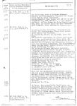
Photo 2. The record in the U 96's War Diary, 31st October 1941, describing attack on a convoy [1]
22:40 - Running in to attack. Unfortunately the night is very bright as the moon is unobscured. It is too dark for an underwater attack on the guarded convoy. To approach, took advantage of a cloud bank covering the moon which, contrary to expectations, moves away quickly. Therefore shots must be made from a long distance.
Shots were made on the middle column.
Four independently aimed shots on the largest ships.
Two hits amidships on an 8000 GRT passenger steamer (two full length decks) and on 5000 GRT freighter. A torpedo apparently running too slow, breaks the surface on firing and is almost overtaken by the boat moving at high speed.
Firing data: target speed 8,5 knots,
angle on the bow: bow left, 80-70 degrees,
deflection angle: 16-15 degrees
torpedo running time: 4 minutes 20 seconds, 3900 meters
Running time of the second torpedo not noted.
Attack position: BE 1125
Boat was seen by the escorting gunboat behind which the approach was made. The gunboat fires approximately 8.8 cm guns and smaller caliber as we were turning for stern shot. Salvos are long, bearing good. Gunboat turns toward and sets white masthead lantern.
Crash dive to 70 meters.
The incident with Reina Victoria
In the Buchheim's novel, one more torpedo attack was described. During her cruise from Gibraltar Straight to France, U 96 meets Spanish ship Reina Victoria, which was almost torpedoed and sunk. In the film adaptation of the book, this incident was skipped. Below, the suitable novel fragment is quoted.
»Also gut!« stößt der Kommandant wie von jäher Wutüberwältigt hervor und gibt den Befehl: »Rohr eins – klar zum Unterwasserschuß!« Der Kommandant atmet tief durch, dann gibt er halblaut –als handele es sich nur um eine Nebensächlichkeit, auf die keine besondere Betonung mehr verwendet werden muß, den Feuerbefehl für Rohr eins. Ein deutlicher Ruck durchfährt das Boot: Der Torpedo hat das Rohr verlassen. »Schuß aus Rohr eins ist elektrisch gefallen!« kommt von unten Meldung. Der Obersteuermann setzt das Glas ab. Der I WO auch. Wir stehen alle wie angewurzelt, die Gesichter gegen die funkelnden Bulleyeketten gerichtet. Du mein Himmel, was wird das geben? Dieses Riesenschiff! Passagierdampfer! Sicher bis in alle Winkel voller Menschen. Gleich werden sie zum Himmel fahren. Oder in ihren Kabinen absaufen. Unser Torpedo kann gar nicht fehlgehen. Das Schiff hat ja keine Fahrt. Keine Vorhaltrechnung. Die glatte See. Die Torpedoeinstellung: zwei Meter unter der Wasserlinie – genau mittschiffs gezielt. Die ideale Entfernung. Ich starre mit weit aufgerissenen Augen auf den Dampfer. Schon projiziert sich das Vorstellungsbild einer gewaltigen Detonation auf die blinkende Silhouette. Ich sehe, wie das ganze Schiff sich aufbäumt, wie die zackigen Fetzen in den Himmel steigen und der riesige Qualmpilz hoch wächst. Die weiße Glut, die rote Glut!Mir staut sich die Luft. Wann kommt endlich der Hammerschlag der Detonation? Die Lichterketten des Dampfers beginnen zu tanzen. Das macht das starre Hinsehen. Ich atme nicht mehr. Da schlagen Worte einer Meldung an mein Ohr: »…Torpedo läuft nicht!« Was? Wie? Wer war das? Das kam doch von unten! Das war eine Meldung aus dem Horchraum! Torpedo läuft nicht! Ich habe doch deutlich den Ausstoß gespürt. Und jetzt? »Kein Wunder«, sagt der Obersteuermann und atmet tief auf. Torpedo läuft nicht. Das heißt: funktioniert nicht. Die Fliegerbombe! Ja, das ist es: Die Fliegerbombe hat auch diesen Torpedo erwischt. Die Druckwelle – natürlich. Das kann ja kein Torpedo ausgehalten haben. Ein Omen! Ein Fingerzeig! Und nun? Rohr zwo, Rohr drei, Rohr vier? »Dann probieren wirs eben mit Rohr fünf«, höre ich den Alten und gleich darauf seinen Befehl: »Heckrohrschaltung!« Schon folgen die nötigen Maschinen- und Ruderbefehle, um das Boot zu wenden – ruhig, wie im Manöver. Rohr fünf! Den anderen Torpedos in den Bugrohren traut der Alte also auch nicht – aber der im Heckrohr, der hat vielleicht nichts abgekriegt. Der Alte läßt es also nicht sein. Auf Fingerzeige reagiert er nicht. Braucht schon ordentliche Staucher. Das Boot kommt langsam in Fahrt und dreht an. Das illuminierte Schiff, das wir eben noch voraus hatten, schiebt sich allmählich nach steuerbord und rückt dann achteraus. Nur noch zwei, drei Minuten, dann müssen wir es genau über dem Heck haben: Schußposition für Rohr fünf.
The incident with Reina Victoria was inspired by event from 3rd December 1941, when U 96 met Spanish passenger ship Cabo de Hornos.
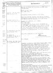
Photo 3. The record in the U 96's War Diary, 3rd December 1941, describing the incident with Cabo de Hornos [1]
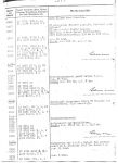
Photo 4. The record in the U 96's War Diary, 3rd December 1941, describing the incident with Cabo de Hornos [1]
04:00 - On course 0 degrees.
05:38 - Steamer in sight bearing 240 degrees. Closed, steamer is steering SE-course. Passenger superstructure. Spanish markings. Brightly lit. Size and course made him appear suspicious. Used searchlight in order to request him to stop. Gives name "Cabo de Hornos". Requested to send papers in English and Spanish language. Steamer acknowledges. It remains stopped, nothing happens.
06:52 - Radio message to B.d.U. transmitted: Is not received by administration and is acknowledged only at 08.12 hours.
"Large passenger steamer "Cabo de Hornos" Spanish markings, steering SE, questioned about status. CG 5467."
After approximately one hour nothing happened, with renewed demand he answered with international signal groups "forziere pp". Morsed in Spanish that if the boat is not launched within 10-minutes, torpedoing will take place.
05:43 - 08:00 - Various courses.
07:37 - After 15-minute stern shot fired on stopped ship. It fails, likely an effect of the aerial bombs. Before the second shot boat is in the water. Papers aboard at 08.00 hours. Are correct. On the way from Buenos Aires to Bilbao by way of Lisbon.
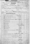
Photo 5. The first page of the report (Schussmeldung) from the attack on Cabo de Hornos [1]
| 1 | Interval between torpedoes in the salvo (in seconds) and spread angle (in degrees) |
| 2 | Torpedo type, serial number |
| 3 | Torpedo speed and running distance |
| 4 | Torpedo depth |
| 5 | Serial number and type of the pistol |
| 6 | Pistol setting |
| 7 | Pistol arming distance |
| 8 | Designation of the torpedo tube |
| 9 | Ejection method (submerged, by means of the piston/surfaced, without piston) |
| 10 | Own speed |
| 11 | Own course |
| 12 | Target bearing |
| 13 | Gyro angle |
| 14 | Aiming station (bridge/conning tower/control room), aiming device (UZO/attack periscope/night periscope) and torpedo calculator type |
| 15 | Aiming point |
| 16 | Torpedo course |
| 17 | Firing data (target speed, angle on the bow, deflection angle) |
| 18 | Depth at the moment of torpedo launch (only for U-Boats) |
| 19 | State of trim at the moment of torpedo launch (by ships etc. heeling at the shot) |
| 20 | Estimated range and observed running time |
| 21 | Observed anomalies in the torpedo run |
| 22 | Launched on the steady course/while turning |
| 23 | Gyro angle |
| 24 | For type G7e torpedoes and range over 3000 m: a) last charging before launch; b) last heating before launch; |
Photo 6. The second page of the report (Schussmeldung) from the attack on Cabo de Hornos [1]
Straight shot to the stationary target. Torpedo malfunctioned. The reason: two aerial bombs on 31st November 1941. Probably they damaged the battery or depth-control gear.
In conclusion, obviously, analyzing the dialogues in the Buchheim's novel and Petersen's movie with respect to the historical procedures does not make sense. Therefore, this article should be treated as a kind of entertainment. All the same, the attention to details is visible in the novel as well as in the movie.
References: