
")
Aiming with the periscope
The Kriegsmarine regulations, M. Dv. 416 Torpedo-Schießvorschrift für U-Boote and M. Dv. 906 Handbuch für U-Bootskommandanten, contain parts, where the torpedo attack without fire control system is described. In case of M. Dv. 416 these parts are: chapters I B and III B “Fächerschuß mit festem Schußwinkel und Sehrohr ohne Anlage”, while in case of M. Dv. 906: paragraphs 146 – 153. These procedures were provided for the situation, when the fire control system was out-of-order (in particular, if the target bearing and gyro-angle transmitting subsystems or torpedo calculator itself were damaged). Then, the torpedo attack with fixed gyro angle was conducted.
After determining the target course parameters (speed and angle on the bow), the torpedo deflection angle β was calculated by means of the tables, the torpedo calculating disc or the torpedo calculator (if operational). The deflection angle was the angle between the torpedo course and target bearing line in the moment of torpedo launch.
There were two types of the torpedo attack: torpedo attack with the fixed gyro-angle (in M. Dv. 906 this angle was equal to 45° and 90°, while in M. Dv. 416 its sample value was equal to 20°) and the direct bow launch (that is the fixed gyro-angle with value equal to 0).
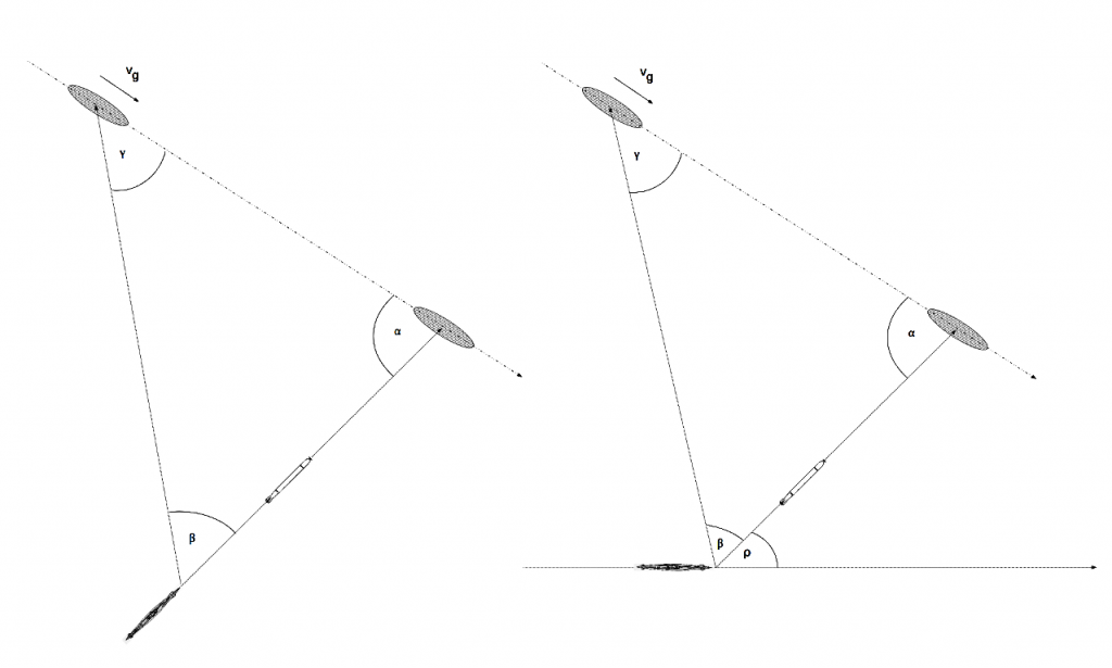
Drawing 1. The direct bow attack and the attack with the fixed gyro-angle
To make torpedo aiming easier, the U-Boat periscopes (both attack and night periscope) were fitted with appropriate equipment.
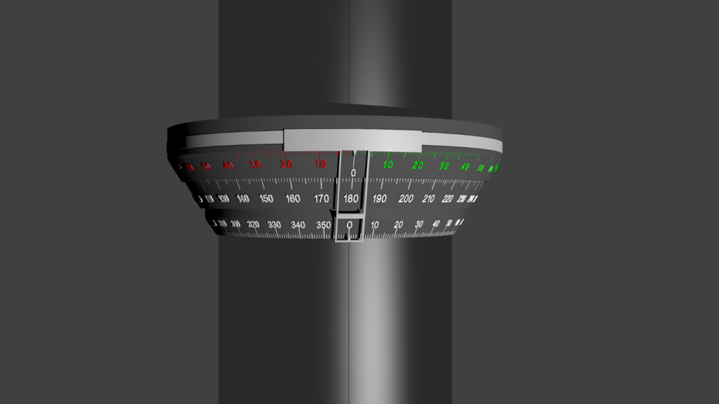
The type NLSR C/9 (Nacht-Luft-Sehrohr) night periscope was fitted with two graduated rings (azimuth circles). They were located one above the other, coaxial with the periscope tube and fixed to the upper part of the U-Boat hull, just under periscope stuffing-box. Both azimuth circles had bearing scales in range from 0 to 360° and fixed so, that 0 mark of upper ring and mark 180° of the lower ring were directed toward the U-Boat bow. Both circles were used to read-out the bearing (relative to the bow), the periscope was pointed to.

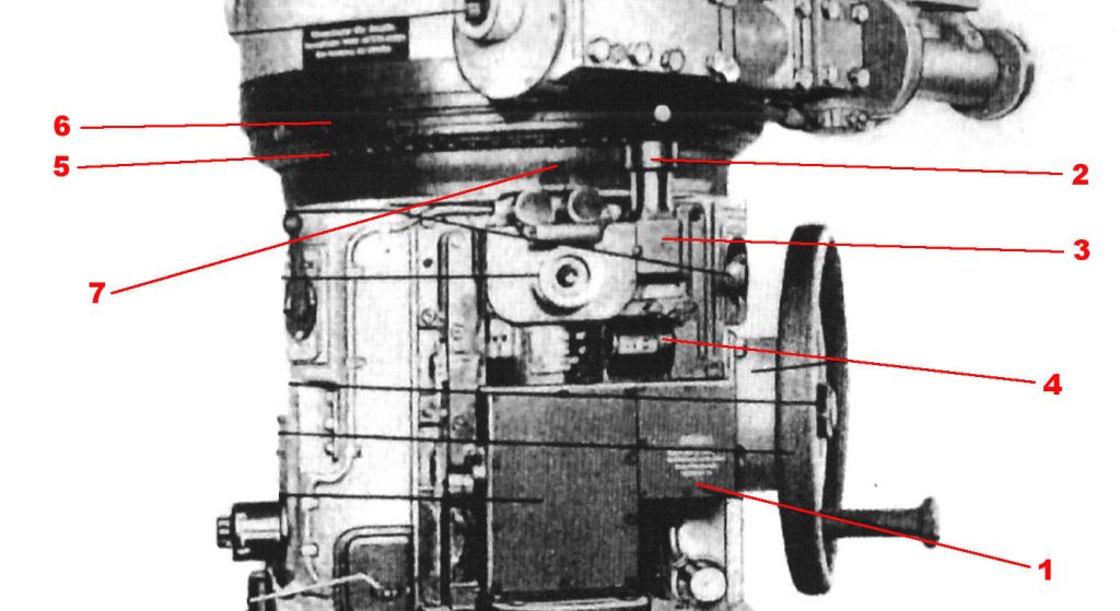
Photo 1. The azimuth circles of the night periscope [1]
| 1 | The screw for locking the deflection angle ring (Vorhaltschieber) |
| 2 | The lower azimuth circle |
| 3 | The upper azimuth circle |
| 4 | The deflection angle ring (Vorhaltschieber) |
| 5 | The deflection angle indicator |
| 6 | The screw for locking the deflection angle indicator |
| 7 | The support plate for electric lamps highlighting the azimuth circles |
| 8 | The cover shielding the electric lamps |
| 9 | The power cable |
| 10 | The electric bulb |

Drawing 2. Azimuth circles of the night periscope
The lower azimuth circle, the one directly adjacent to the periscope tube, made possible reading of the bearing from the „outside”, when not looking through the periscope. Along the periscope tube, exactly over the ocular, the indication line was engraved. When the periscope was directed toward the bow, this line was under 0 mark of the lower azimuth circle.
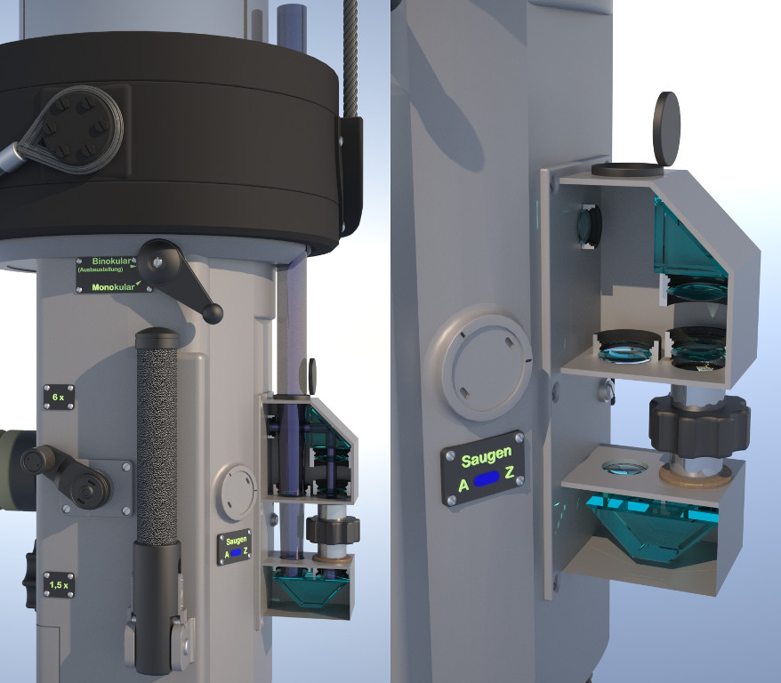
The ocular box of the type NLSR C/9 night periscope was fitted with additional optical system (kind of telescope), which made possible reading of the bearing while looking through the periscope. The bearing scale was visible in the upper part of the view field. This optical system consisted of prisms and lens, and transmitted the view of the bearing scale through the slit in the periscope collar to the ocular box interior.
Because this optical system was located at the back side of the ocular box, to keep the bearing value valid, the upper azimuth circle had to be rotated by 180° in relation to the lower circle. So, when the periscope was directed toward the bow, the optical system transmitted the 0 mark of the upper azimuth circle.
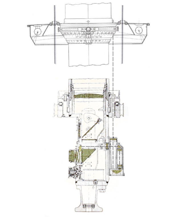
Drawing 3. The cross-section of the type NLSR C/9 periscope ocular box (the optical system for transmitting bearing scale is visible)
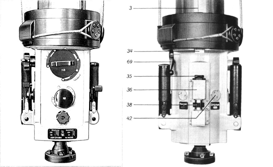
Drawing 4. The ocular box of the type NLSR C/9 periscope [2]
| 3 | The engraved indication line |
| 34 | The slit in the periscope collar |
| 35 | The objective of the optical system for transmitting the bearing from the upper azimuth circle |
| 36 | The casing of the optical system for transmitting the bearing from the upper azimuth circle |
| 38 | The focus adjusting knob of the optical system for transmitting the bearing from the upper azimuth circle |
| 42 | The plug of the port for connecting periscope drying equipment |
| 69 | The lever for engaging the additional focusing screen, which made possible usage of the upper ocular of the periscope |
Above two fixed azimuth circles was a deflection angle ring (Vorhaltschieber) located. It had graduated scale in range 60° – 0 – 60° and could be rotated in relation to the azimuth circles.
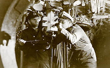
Photo 2. Oblt. Erich Topp looking through the night periscope in U 552's control room (on the back side the optical system for transmitting the bearing is visible)
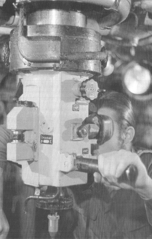
Photo 3. The ocular box of the night periscope with the optical system for transmitting bearing visible
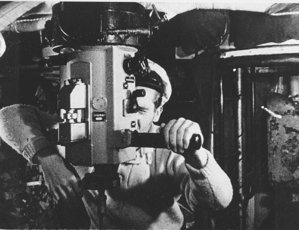
Photo 4. The ocular box of the night periscope with the optical system for transmitting bearing visible
Drawing 5. The ocular box of the night periscope with the optical system for transmitting bearing visible [3]
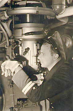
Photo 5. The night periscope in the control room (the shield covering the electric lamps is visible)
Drawing 6. The visualization of the azimuth circles and deflection angle ring of the night periscope
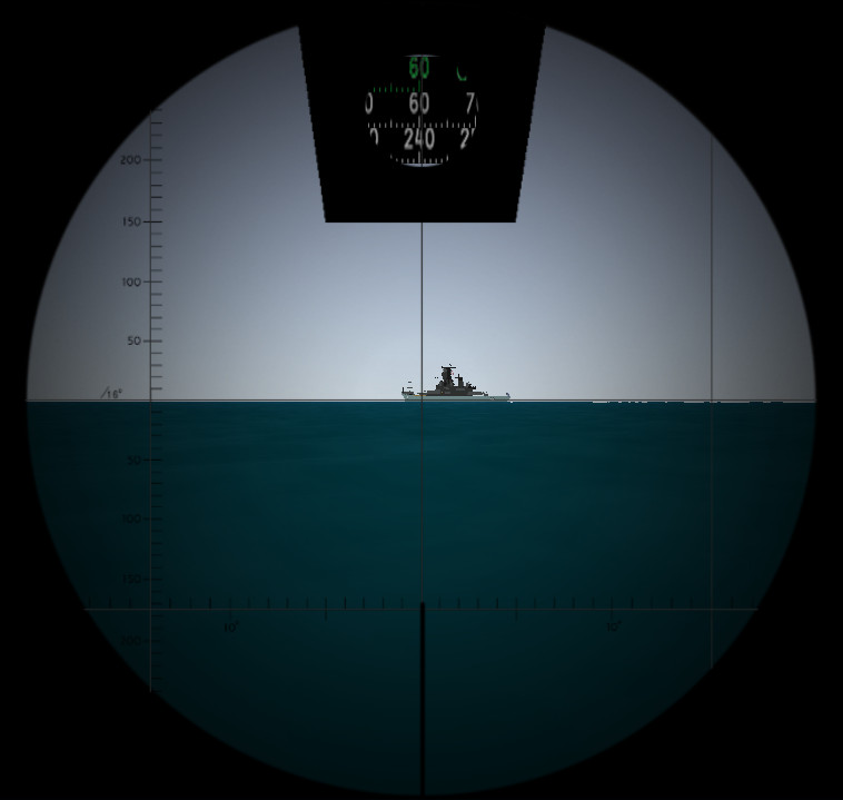
Drawing 7. The visualization of the view through the night periscope (two bearing scales and the scale of the deflection angle ring are visible)
The torpedo attack with fixed gyro-angle was conducted as follows: after reaching the attack position in front of the target, knowing the target course parameters (speed and course, which were determined during over-hauling maneuver), the deflection angle β (Vorhaltwinkel) was calculated by means of the torpedo calculating disc, the torpedo calculator (if operational) or the tables (Vorhalttabelle). The deflection angle was calculated for the angle on the bow γ = 90° in the moment of torpedo launch.
There was an addendum to the regulations M. Dv. 416 Torpedo-Schießvorschrift für U-Boote: a collection of tables M. Dv. 416 Tabellenheft zur Torpedo-Schießvorschrift für U-Boote. This collection contained four tables (for four torpedo speeds: 30, 40, 44 and 50 knots) with pre-calculated values of the deflection angles β for different values of the angle on the bow γ and target speed vg.
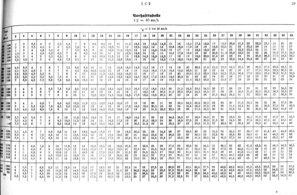
Drawing 8. Vorhalttabelle for torpedo speed 40 knots [4]
Then the torpedo course was calculated using the following formula:
- if attacking starboard side of the target: bearing perpendicular to the target course + deflection angle β
- if attacking port side of the target: bearing perpendicular to the target course - deflection angle β
For example, if the target was cruising on course 40°, its speed was 13 knots, and the torpedo was moving with the speed 30 knots, the deflection angle (assuming the angle on the bow γ = 90° in the moment of launch) was β ≈ 26°.
When attacking starboard side, the torpedo course was 336°.
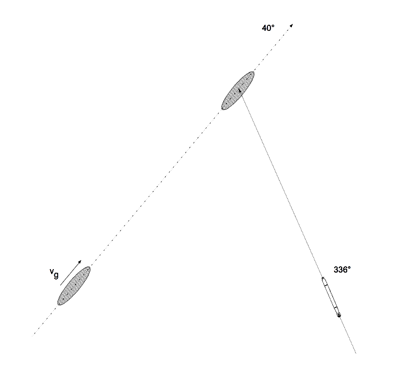
Drawing 9. The target and the torpedo course
Then, depending on the tactical situation, the commander decided what value of the gyro-angle ρ should be.
If the course of the U-Boat was the same as the course of torpedo or only a small turn to achieve such course was needed, then the value of the gyro-angle ρ was small or even equal to 0. However, if achieving of such course would require a large turn (which would take too much time, for example, the submerged U-Boat cruising with the speed of 4.5 knots, made 70° turn at full rudder for over 80 seconds), the necessary turn was decreased by using larger value of the gyro-angle ρ.

Drawing 10. The torpedo and the U-Boat course while conducting direct bow attack (large turn is required to achieve attack course)
The pre-calculated tables contained firing data for the following values of the gyro-angle ρ: 0, 15°, 30°, 45°, 60°, 75°, 90°.
After choosing the most convenient gyro-angle ρ, the new attack course was calculated (that is the course, which should be achieved by U-Boat in the moment of the torpedo launch) using the following formula:
- if attacking starboard side: bearing perpendicular to the target course + (deflection angle β + gyro-angle ρ)
- if attacking port side: bearing perpendicular to the target course - (deflection angle β + gyro-angle ρ)
For the example situation, when the torpedo course was 336°, let's assume, that the U-Boat was cruising on course 45°. To achieve the course 336° (in order to conduct direct bow attack), the large turn of 69° would be required. If (for tactical reasons) there was no time to do this (i.e. due to small distance to the target and necessity of the immediate attack), the required turn was decreased to value 9° by choosing the gyro-angle ρ = 60° port (that is torpedo would run on the course equal to 300° in relation to the U-Boat bow). So the final attack course of the U-Boat was equal to 36°. After issuing the turn order to the helmsman, the selected gyro-angle value was passed to the torpedo room to be set on torpedoes.
Drawing 11. The torpedo and the U-Boat course while attacking with the fixed gyro-angle (small turn is required to achieve attack course)
Then the values of the deflection angle β and the selected gyro-angle ρ were set on the periscope in the following way:
- the trainable deflection angle indicator was rotated so as to indicate the torpedo relative course (that is 300°) at the lower azimuth circle;
- the deflection angle ring (Vorhaltschieber) was rotated in such way, that locked deflection angle indicator pointed the calculated value of the deflection angle β = 26° at the side described as Gegner Bug Rechts (because the target bow was pointing right);
- after unlocking the deflection angle indicator was rotated so as to point mark 0 at the locked deflection angle ring;
- the locked deflection angle indicator pointed at the lower azimuth circle the bearing, the periscope had to be set to: 274°;
Now, the angle between the periscope bearing and the torpedo course (after its turn by gyro-angle ρ) was equal to β.
Drawing 12. The setting of the azimuth circles during the torpedo attack with the fixed gyro-angleo
After reaching the attack course and setting the periscope, the commander had to wait, until the target (visible under the angle on the bow γ = 90°) appears in the periscope graticule. In that moment, the torpedo had to be launched.
If the deflection angle β was calculated by means of the tables or calculating disc, the result did not include parallax, resulting from the torpedo turn and non-zero distance between the torpedo tubes and the periscope. The linear parallax correction for given values β and ρ could be found in the tables (Schusstafel).

Drawing 13. The cover and the first page of the tables with the parallax corrections
Drawing 14. The page with the table containing values of the parallax corrections
The rows of the tables contain the corrections value for different values of the angle on the bow (30°, 40, 50°, 60°, 90°, 120°), while the columns contain values for different target speed (10, 20, 30, 40 knots). The correction should be read from the proper part of the table, corresponding to the chosen torpedo course (that is gyro-angle). In the example situation (gyro-angle ρ = 60° that is torpedo course 300°, angle on the bow γ = 90°, target speed 13 knots), the correction read from the table had value ~52 meters (the interpolated value between the values 60 and 34 meters for speed 10 and 20 knots respectively).
The correction was given in the linear form (contrary to the angular correction used in the torpedo calculator). It required to launch torpedo when the target was located in the distance equal to the linear correction value from the aiming point. While aiming the torpedo, in order to take a proper lead (which can be negative or positive), the commander had to correctly estimate the target dimensions, however, he did not need to know the accurate distance to the target (as in the case of the angular correction).
So, for the example tactical situation, the target had to pass the aiming point by ~52 meters. Assuming, that the target is type Liberty merchant ship (length ~130 meters), in order to hit the midship, the torpedo had to be launched, when target stern (not midship) appeared in the periscope graticule.
Drawing 15. A linear parallax correction while aiming torpedo
The angular parallax correction calculated by means of the torpedo calculator model for the distance to the target equal to 1200 meters, has value ~3°, that is ~60 m of the linear correction.
Generally, it was recommended to attack with the gyro-angle as small as possible, because the parallax correction was the smallest.
The type StaSR C/2 (Stand-Sehrohr) attack periscope located in the U-Boat conning tower was fitted similarly to the night periscope. The fixed azimuth circle with graduated scale in range from 0 to 360° was located in its upper part. The mark 180° of the scale was directed toward the bow. On the periscope casing, directly over the ocular, the indicator was fitted, which made possible reading of the current bearing when not looking through the periscope.
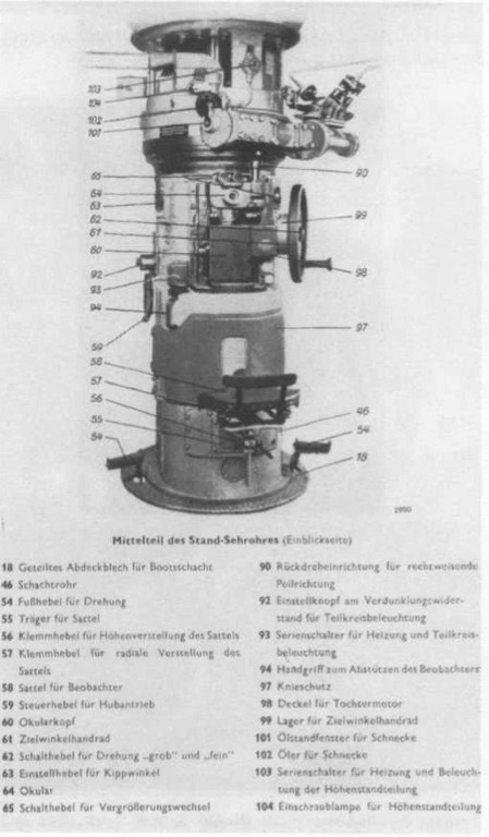
Drawing 16. Type StaSR C/2 attack periscope [5]
| 18 | The flange covering the periscope well |
| 46 | The periscope casing |
| 54 | The foot lever for periscope training |
| 55 | The saddle support |
| 56 | The saddle height adjusting lever |
| 57 | The saddle position adjusting lever |
| 58 | The saddle |
| 59 | The periscope winch control lever |
| 60 | The ocular box |
| 61 | The hand-wheel for manual training of the periscope |
| 62 | The training mode switch (coarse/fine) |
| 63 | The lever for controlling the periscope head elevation angle |
| 64 | The periscope ocular |
| 65 | The lever for changing magnification |
| 90 | The coupling of the azimuth circle with the gyro-repeater by means of the differential gear |
| 92 | The regulating knob for adjusting the azimuth circle highlight |
| 93 | The heating and lighting switches |
| 94 | The handle |
| 97 | The knees protection |
| 98 | The gyro-repeater cover |
| 99 | The bearing of the hand-wheel for manual training of the periscope |
| 101 | The sight-glass for inspecting the hydraulic oil level in the periscope power-drive installation |
| 102 | The greasing point |
| 103 | The switches of the heating and lightning of the upper part of the periscope |
| 104 | The lamp illuminating the upper part of the periscope |
The attack periscope was also fitted with the optical system for showing the bearing scale inside the view field of the periscope. Because this system was located at the same side of the ocular box as the ocular, the second azimuth circle shifted by 180° was not needed (contrary to the case of night periscope). The optical system transmitted the same value as indicated by the external bearing indicator.
Over the fixed azimuth circle, the trainable deflection angle ring was located, which was used in the same way as in the case of the night periscope.
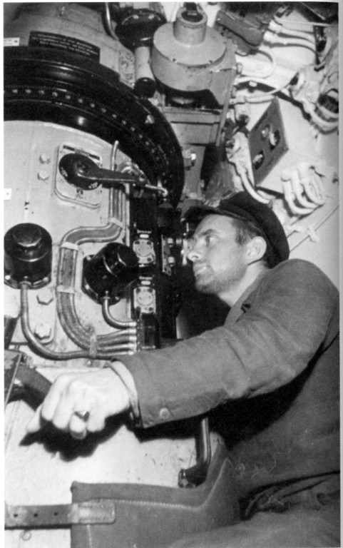
Photo 6. KrvKpt. Reinhard Suhren at the attack periscope in U 564's conning tower (the single azimuth circle is visible) [6]
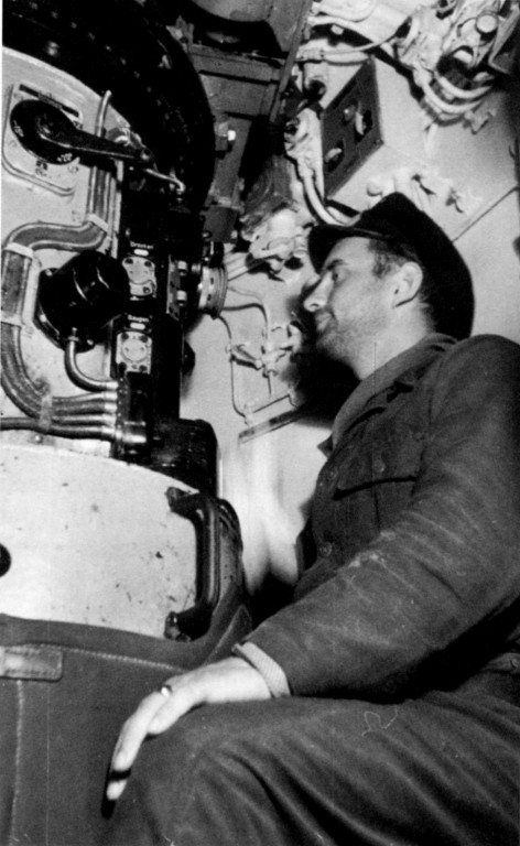
Photo 7. KrvKpt. Reinhard Suhren at the attack periscope in U 564's conning tower (the single azimuth circle is visible) [6]
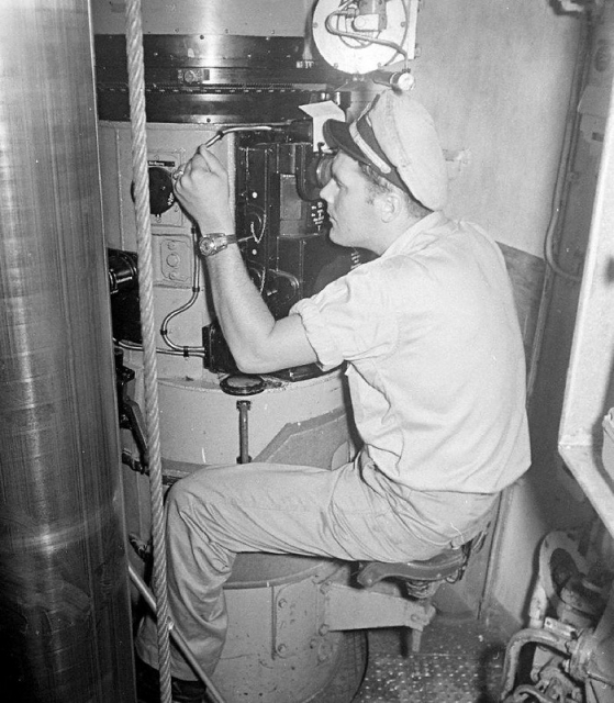
Photo 8. The attack periscope in U 234's conning tower (the single azimuth circle is visible)
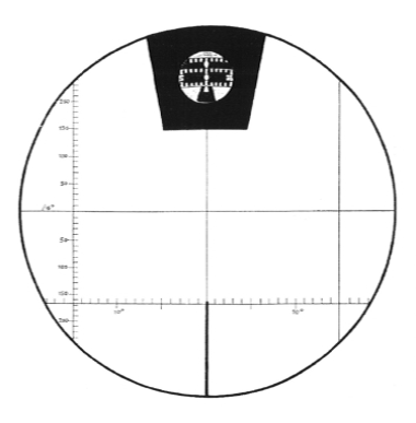
Drawing 17. The graticule of the attack periscope [2]
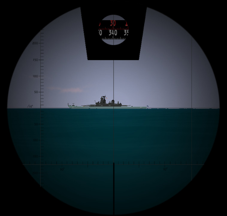
Drawing 18. The visualization of the view through the attack periscope (the bearing scale and the scale of the deflection angle ring are visible)
The attack periscope was also fitted with the additional gear for reading the true bearing (that is bearing relative to the north direction) (Germ. Peilrichting). This gear consisted of the gyro-repeater embedded just below the ocular, the gear for coupling the fixed azimuth circle with the differential gear, the differential gear and the four-digit mechanical counter.
Drawing 19. The gear for reading the true bearing [5]
| 1 | The gyro-repeater |
| 2 | The gear for coupling the fixed azimuth circle with the differential gear |
| 3 | The differential gear |
| 4 | The four-digit mechanical counter |
| 5 | The azimuth circle |
| 6 | The deflection angle ring |
| 7 | The external bearing indicator |
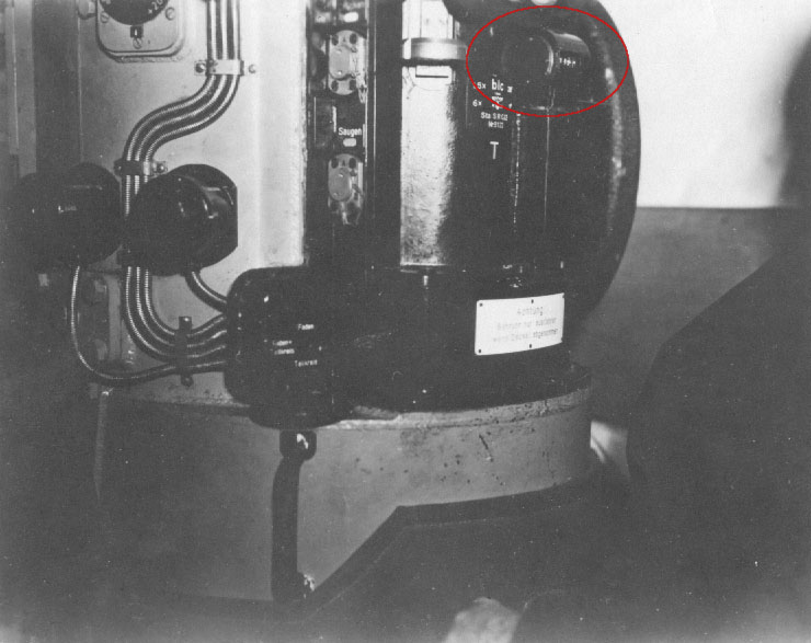
Photo 9. The four-digit mechanical counter at the attack periscope in the U 570's conning tower [7]
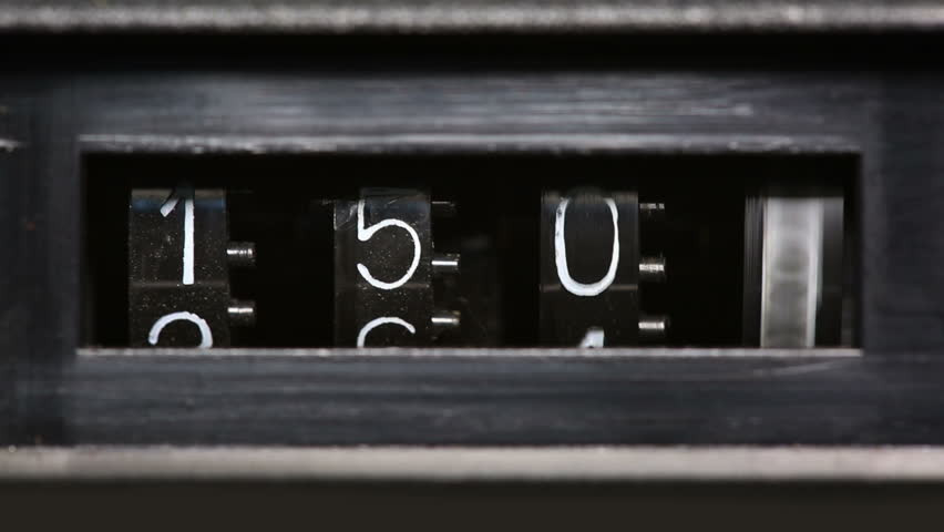
Photo 10. The four-digit mechanical counter (sample photo)
The relative bearing (measured relative to the bow) was transmitted by means of the coupling gear to the differential gear. The differential gear was also connected with the gyro-repeater, which received the U-Boat course. The differential gear added these two values, calculating in the result the true periscope bearing. The value of the true bearing was displayed on the four-digit mechanical counter (with the accuracy of 20 minutes of arc).
The ability of reading the true bearing makes easier usage of the periscope for the navigation (i.e. taking shore bearing or issuing orders for entering course equal to the periscope true bearing) and attack (i.e. making combat plot) purposes.
In the control room of the U 995 (located in the Laboe type VIIC U-Boat converted to museum-ship) is installed the type ASR C/13 (Angriff-Sehrohr) periscope. This is post-war periscope designed by Zeiss, based on the war-time type ASR C/6 periscope, which was designed for type XXIII U-Boats. This periscope consisted of the ocular box of type NLSR C/9 night periscope and periscope head of the type StaS C/2 attack periscope. Type ASR C/13 periscope which can be seen in the U 995 control room comes most likely from the U-Hai or U-Hecht (ex U 2365 and U 2367 respectively) and was installed on U 995 in the time when (most likely) she was converted to the museum-ship (during her service in the Royal Norwegian Navy as KMN Kaura, in the control room was installed the original type NLSR C/9 periscope).
The ocular box of the type ASR C/13 periscope is simplified version of the type NLSR C/9 periscope ocular box. It is slightly smaller, however the layout of the oculars, knobs and levers is the same. The ocular box is not fitted with the optical system for showing the bearing scale in the view field (the system was probably abandoned to make the manufacture simpler, faster and cheaper). The current periscope bearing is indicated by indication line, engraved on the periscope tube. It points the current bearing at the fixed azimuth circle. That's why type ASR C/9 periscope is fitted with only one azimuth circle, with 180° mark directed toward to the bow (please note, that azimuth circle in the U 995 control room is not properly set relative to the U-Boat longitudinal line). Over the fixed azimuth circle, the deflection angle ring is located, which is used in the same way as in case of previously described periscopes.
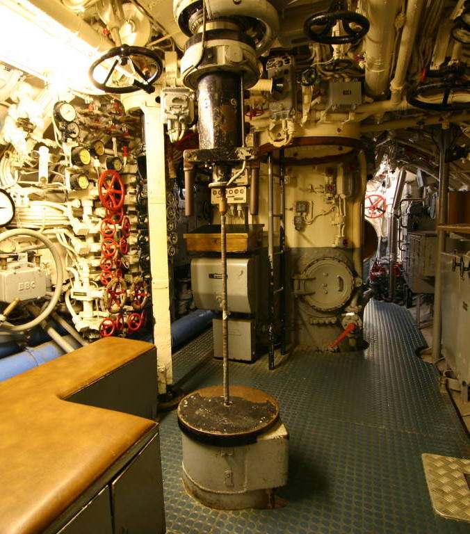
Photo 11. The type ASR C/13 periscope in the U 995's conning tower (back side view)
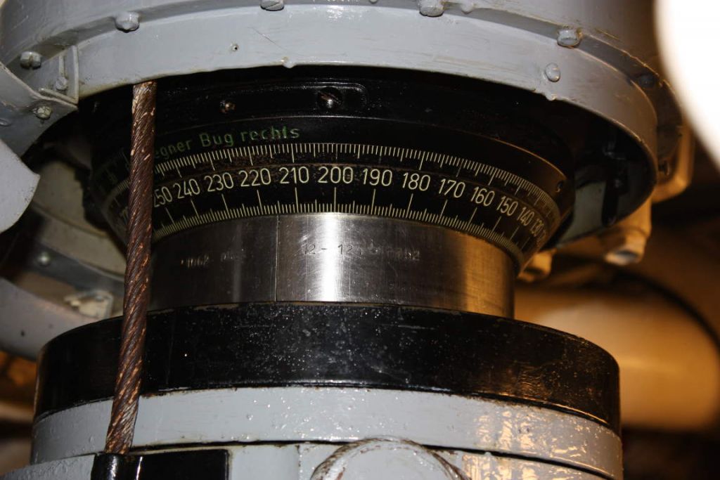
Photo 12. The part of the tube of the type ASR C/13 periscope with engraved indication line visible, pointing the bearing 224° (the deflection angle ring above is also visible)

Drawing 20. The graticule of the type ASR C/13 attack periscope

Drawing 21. The visualization of the view through the type ASR C/13 attack periscope C/13
References:
[1] Carl Zeiss Archiv
[2] Harry Schlemmer, Vom Turmsehrohr zum Optronikmast. Geschichte der Zeiss U-Boot-Sehrohre
[3] Courtesy of Simon Morris
[4] Tabellenheft zur Torpedo-Schießvorschrift für U-Boote, 1940
[5] Fritz Köhl, Axel Niestle, Vom Original Zum Modell - U-Boot Typ VIIC
[6] Lawrence Paterson,U-Boat War Patrol - The Hidden Photographic Diary of U564
[7] Photographs taken during inspection by U.S. Naval Officers - Enclosure C of ONI Report