
")
Influence of estimation errors
One of the many ways for a vessel to avoid being torpedoed that comes to mind is to impede the enemy’s ability to correctly estimate the angle on the bow, the vessel’s speed, and the distance to the vessel. This could be accomplished by painting their hulls with complex geometrical patterns using contrasting colors. It was called dazzle camouflage. At first glance it seems like that type of camouflage would attract attention rather than cloak the vessel but due to the irregular, well designed geometric patterns, an observer would find it difficult to determine the direction the target is heading and would also have trouble estimating the angle on the bow. Additionally, false waves could be painted on the bow and stern which made determining the direction and speed of the target even more difficult.
Moreover, operation of coincidental range finders – which required adjusting two images – was also impeded because due to the irregular painting, even ideally matched images didn’t look right to the observer.
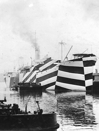
Photo 1. Merchant USS West Mahomet painted with dazzle camouflage [1]

Photo 2. Aircraft carrier HMS Argus painted with dazzle camouflage [2]
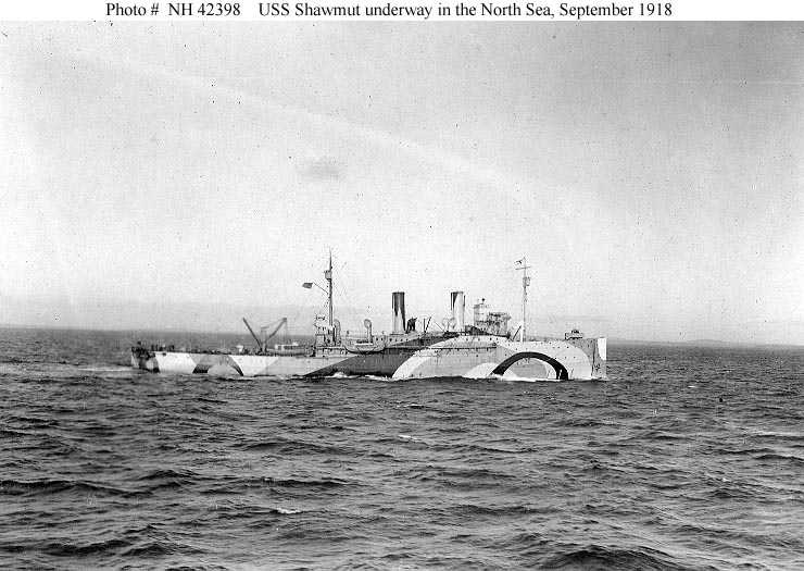
Photo 3. Minelayer USS Shawmut painted with dazzle camouflage [3]

Photo 4. U 253 painted with dazzle camouflage
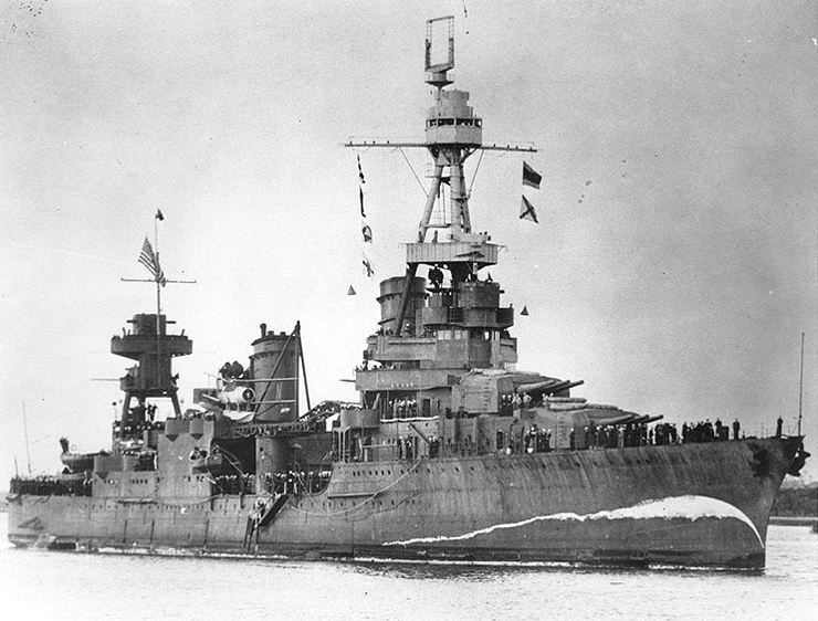
Photo 5. Heavy cruiser USS Northampton with false bow wave [4]
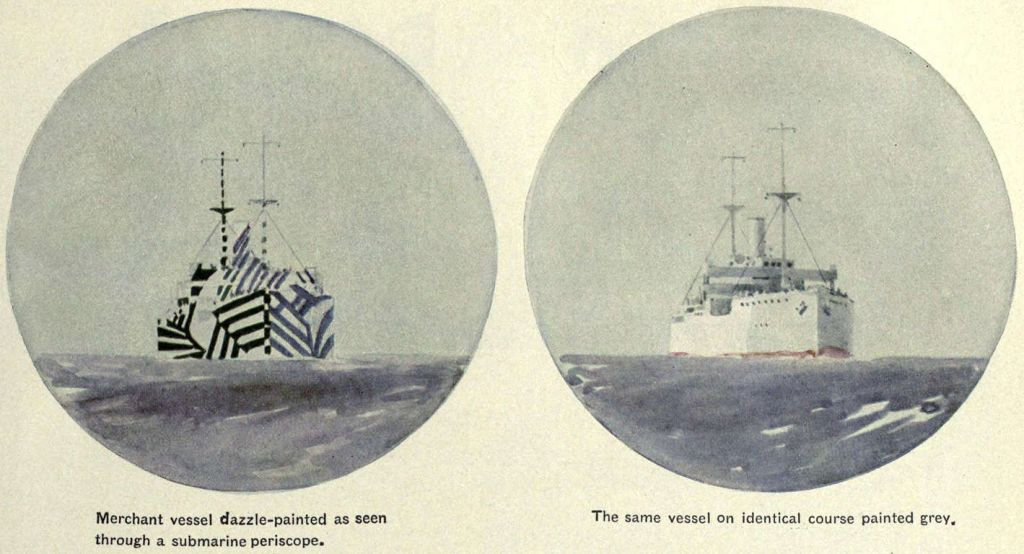
Photo 6. Artist's conception of periscope view of a merchant ship in dazzle camouflage (left) and the same ship uncamouflaged (right) [5]
Over time with the introduction of more advanced coincidental range finders, stereoscopic range finders and radar the value of dazzle camouflage decreased. During World War II it was sometimes used with the aim of puzzling observers on board of submarines where due to lack of space for sophisticated equipment visual observation was the main way of obtaining firing data. However the main type of camouflage became a new painting scheme which softened the vessel’s silhouette between the sea and the horizon in the background.
Because the target vessel is usually a large target it is obvious that there is a range of angles on the bow and target speed (rather than just the exact one) where the torpedo will still hit the target. In other words, there is some permissible error in angle on the bow and speed, where the torpedo still hits the target. For example a torpedo aimed directly at the center of the target with incorrect firing data might still hit the bow or the stern and sink the target.
Generally speaking, the permissible error is greater if the torpedo run is smaller. The shorter the time of the torpedo run the less the target moves - due to incorrect firing data - relative to the calculated impact point. The virtual length of the target as seen by the torpedo, which obviously depends on the real length of the target and the torpedo track angle, is also relevant. The torpedo sees the longest target when her track is perpendicular to the target course (exact formula: target length multiplied by the sine of the torpedo track angle).
That's why, during torpedo attacks, the general rule is to fire from the smallest possible distance and in such a way that the torpedo track angle is closest to a right angle.
The analysis of permissible errors in determining target course parameters is a complex problem because the target hit has to be considered a function depending on two variables: angle on the bow and target speed. Additionally, three other parameters mentioned earlier – length of torpedo run, target length and torpedo track angle have to be taken into account.
Below are the results of a numerical simulation of the torpedo hitting target problem as a two-dimensional matrix containing numbers 0 and 1 (miss and hit respectively). Subsequent matrix rows represent different angles on the bow (the middle row is the real angle on the bow), while subsequent matrix columns correspond to different speeds (the middle column is the real target speed). To see the influence of all parameters, particular matrices were calculated for different lengths of torpedo run and torpedo track angle.
Angle on the bow: 68°
Target speed: 12 knots
Target length: 120 m
Distance to target: 1000 m
Length of torpedo run: 927 m
Track angle: 90,23°

Drawing 1.
Angle on the bow: 68°
Target speed: 12 knots
Target length: 120 m
Distance to target: 2000 m
Length of torpedo run: 1854 m
Track angle: 90,23°

Drawing 2.
Angle on the bow: 68°
Target speed: 12 knots
Target length: 120 m
Distance to target: 4000 m
Length of torpedo run: 3708 m
Track angle: 90,23°
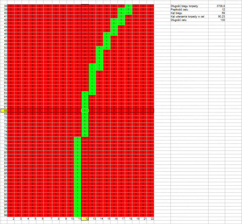
Drawing 3.
Angle on the bow: 30°
Target speed: 12 knots
Target length: 120 m
Distance to target: 1000 m
Length of torpedo run: 754 m
Track angle: 138,46°
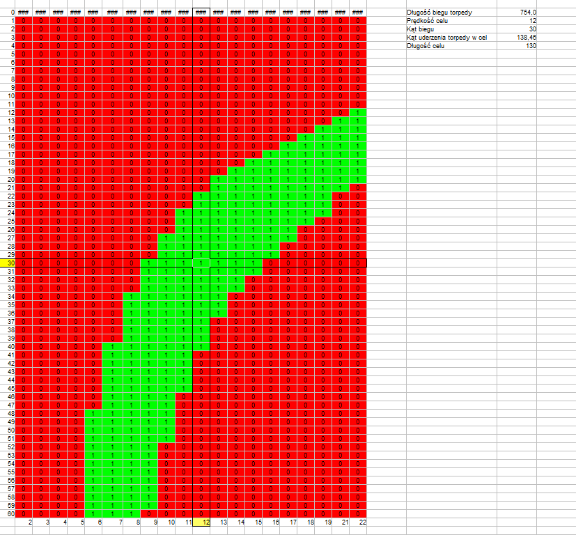
Drawing 4.
Angle on the bow: 30°
Target speed: 12 knots
Target length: 120 m
Distance to target: 2000 m
Length of torpedo run: 1508 m
Track angle: 138,46°

Drawing 5.
Angle on the bow: 30°
Target speed: 12 knots
Target length: 120 m
Distance to target: 4000 m
Length of torpedo run: 3016 m
Track angle: 138,46°
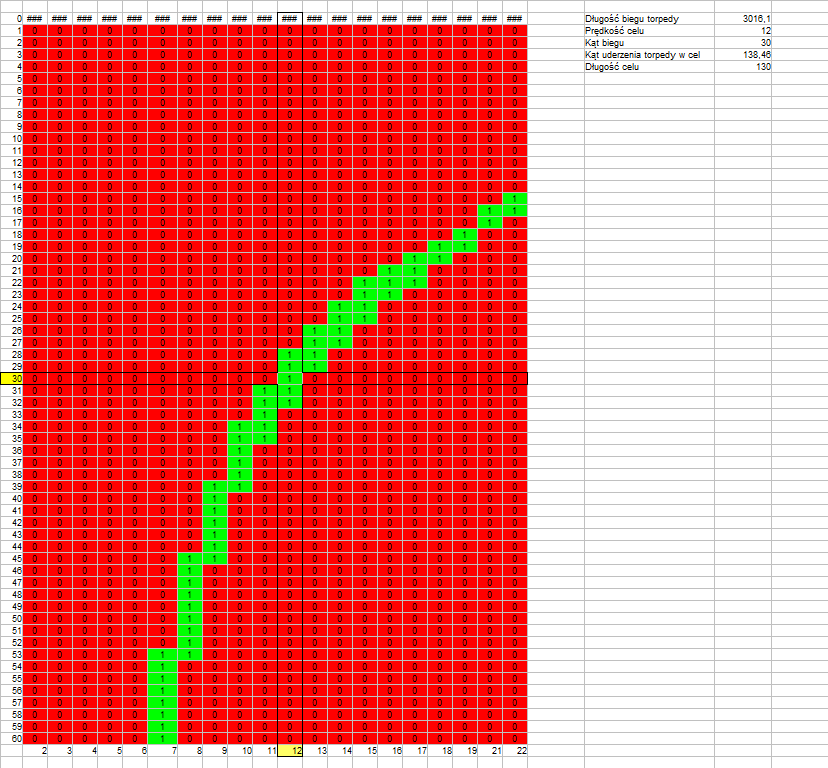
Drawing 6.
Angle on the bow: 56°
Target speed: 20 knots
Target length: 120 m
Distance to target: 1000 m
Length of torpedo run: 829 m
Track angle: 90,45°

Drawing 7.
Angle on the bow: 56°
Target speed: 20 knots
Target length: 120 m
Distance to target: 2000 m
Length of torpedo run: 1658 m
Track angle: 90,45°
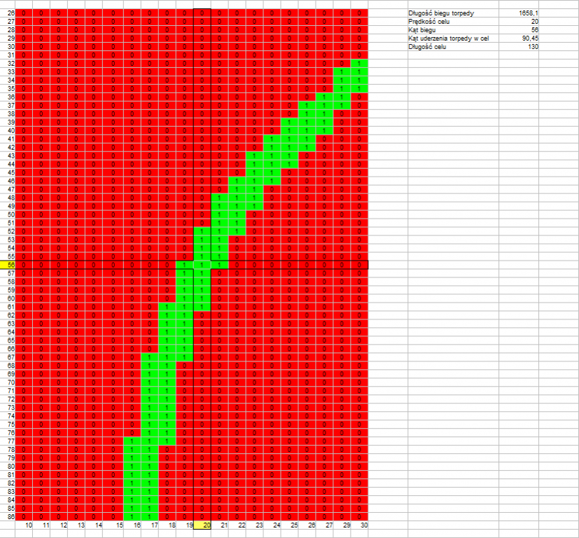
Drawing 8.
Angle on the bow: 56°
Target speed: 20 knots
Target length: 120 m
Distance to target: 4000 m
Length of torpedo run: 3316 m
Track angle: 90,45°
Drawing 9.
Angle on the bow: 111°
Target speed: 20 knots
Target length: 120 m
Distance to target: 1000 m
Length of torpedo run: 1839 m
Track angle: 30,51°
Drawing 10.
Angle on the bow: 111°
Target speed: 20 knots
Target length: 120 m
Distance to target: 2000 m
Length of torpedo run: 3678 m
Track angle: 30,51°
Drawing 11.
Angle on the bow: 111°
Target speed: 20 knots
Target length: 120 m
Distance to target: 4000 m
Length of torpedo run: 7356 m
Track angle: 30,51°

Drawing 12.
The above drawings confirm that what was stated earlier – the permissible error resulting in a hit is greater if the length of the torpedo run is shorter (drawings 1, 4, 7) and if the track angle is closer to a right angle (drawing 1, 2, 3 versus drawing 4, 5, 6).
What is interesting is that there is no visible influence of the real target speed – at twice the target speed, the permissible error is almost the same (drawing 7, 8, 9 versus drawing 1, 2, 3).
Generally speaking, permissible errors in estimating the angle on the bow and target speed are:
|
Distance to target m |
Track angle: 90º |
Track angle: 40º | ||
| target speed | angle on the bow | target speed | angle on the bow | |
| 1000 | ±1 | ±10 | ±2 | ±5 |
| 2000 | ±0,5 | ±10 | ±1 | ±4 |
| 4000 | ±0 | ±5 | ±0 | ±2 |
These summarized values (generated for a few arbitrary sets of parameters) do not present all possible combinations, but they do show the general rule presented in the beginning – the chance to hit is greater the shorter the torpedo run and the closer the track angle is to a right angle.
To increase the chance of hitting a target, torpedo salvos (that is multiple torpedoes are shot, where they run the same course but at different time intervals, or the torpedoes are all fired at the same time but they run on courses differing by a few degrees) were used.
In the later part of World War II, when the Allies reinforced the convoy escorts, commanders of German U-Boats were unable to conduct close range (below 1000 meters) torpedo attacks, so it reduced their effectiveness. As a response, the Germans deployed new manoeuvring torpedoes (FAT and LUT), which could be launched without accurate aiming. They crossed the course of the convoy many times, increasing their chance of hitting something.
References:
[1] USS West Mahomet
[2] HMS Argus
[3] USS Oglala
[4] USS Northampton
[5] Encyclopædia Britannica (1922)