
")
Stabilized azimuth line
In the mid 20's of the twentieth century, some manufacturers of the optical equipment (Zeiss, Nedinsco, Barr & Stroud, Kollmorgen) offered periscopes fitted with feature called Stabilized Azimuth Line (Germ. Feste Linie im Raum). In the field of view of such periscope, the vertical line was visible whose position in space was fixed (stabilized by gyro-repeater). In other words, despite the changes of the U-Boat course and related changes of the field of view, the vertical azimuth line was still in the same place (at the same true bearing, relative to the true north).

Drawing 1. The position of the stabilized azimuth line before and after course change by a few degrees to starboard
The vertical line made possible to measure the target speed accurately (knowing its length), regardless its course (or the angle on the bow actually). To get the target speed, the time interval between passing the vertical line by target bow and target stern was measured. Then, target length (in meters) was divided by time interval (in sec), giving the target speed (in m/sec). To get (approximate) speed in knots, the result should be multiplied by 2.
To make the calculation easier, the dedicated circular slide rules were manufactured, so the result could be get immediately.
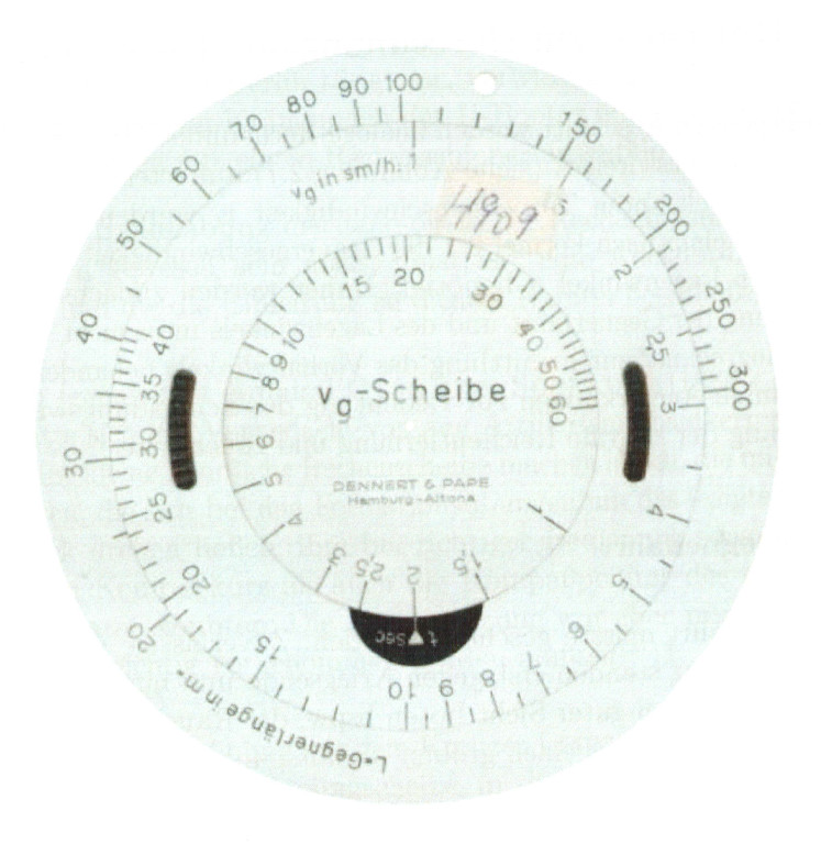
Drawing 2. German circular slide rule (vg-Scheibe) manufactured by Dennert & Pape company [1]
What is important is the fact that the result is irrespective of the angle on the bow (does not depend on the position of the observer relative to the target).
The largest limitation of this method was the influence of the own motion on the result of measurements. The most accurate results were achieved, when own boat was stationary. When own boat was moving, the result depended on the own speed and the target bearing.
The own speed influenced the result slightly only when the target bearing was 0 or 180° and own course was perpendicular to the target course (i.e. the own velocity's component, which is parallel to the target velocity, is equal to 0). The largest influence of the own speed was in case, when target was abeam and own course was parallel to the target course (i.e. the own velocity's component, which is parallel to the target velocity, was the largest, equal to own speed). In the extreme case, when own and target course are parallel and own speed is equal to the target speed, the speed measured by means of this method would be equal to 0.
The other limitation of this method is relatively long time required to measure time and thus a long time of exposure of the periscope head over the water surface (this increased the possibility of spotting). I.e. when measuring the speed of the Admiral Hipper heavy-cruiser (length 212 m) cruising with speed 19 knots, it would take 23 seconds to take the measurement.
The author did not find information about implementation of the stabilized azimuth line component in the German periscopes manufactured by Zeiss company, however based on the manual (dating from 1940) of the American Type 2 periscope (manufactured by Kollmorgen company, type 89KA40/1.414), one can present the general operating principle.
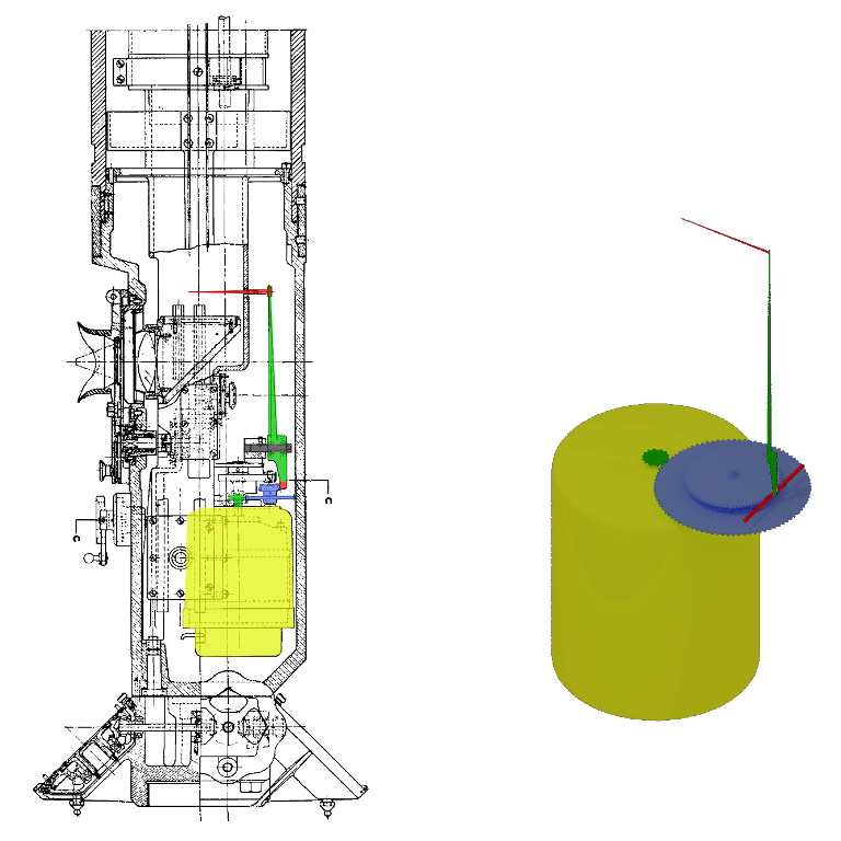
Drawing 3. The stabilized azimuth line component in the American Type 2 periscope manufactured by Kollmorgen company [2]
In the lower part of the ocular box the selsyn receiver (gyro repeater) was located. By means of the set of gears, it moved the gear rack to the one side or another. This gear rack was attached to the lower end of the pointer lever. To the upper end of this lever, the pointer was attached. This pointer was visible in the periscope field of view as a stabilized azimuth line.

Drawing 4. The operating principle of the stabilized azimuth line component in the American Type 2 manufactured by Kollmorgen company
The shaft of the gyro-repeater rotated when the submarine changed her course. The rotation of the shaft was transmitted (by means of the set of gears) at the gear rack which changed the inclination of the pointer lever. As the pointer lever inclination changed, the pointer (visible as the stabilized azimuth line) moved across the periscope field of view to the left or right, to keep the fixed position in space despite the course change.
Regarding the Zeiss periscopes, in the Zeiss Archiv only the following description could be found:
Die Feste Linie im Raum ist eine Zusatzeinrichtung in U-Boot-Sehrohren. Sie dient dazu, die Geschwindigkeit eines Gegnerschiffes aus seiner bekannten oder geschätzten Länge zu ermitteln. Im Gesichtsfeld des Sehrohres erscheint ein senkrechter Faden, der durch den Tochtermotor einer Kreiselkompaß-Mutteranlage raumfest gesteuert wird und daher von Kursänderungen und Kursschwankungen des U-Bootes unbeeinflußt ist, wenn am Sehrohr 6fache Vergrößerung eingestellt ist. Der Faden stellt also eine feste Richtung im Raum dar. Die Bewegung des senkrechten Fadens ist begrenzt und entspricht einem Gesichtswinkel von +/- 3 ½°. Wird der Kurs des U-Bootes bei eingeschaltetem Tochtermotor um mehr als +/- 3½° geändert, so läuft der Faden gegen einen Anschlag und bleibt seitlich im Gesichtsfeld stehen. Der Motor arbeitet über eine Rutschkupplung und läuft dabei ohne Schaden weiter. Mit einem Einstellhebel kann der senkrechte Faden in jede beliebige Lage innerhalb des Beeiches von +/- 3½° gebracht werden. Nach Loslassen des Einstellhebels geht dieser selbsttätig in die Mittellage zurück und der senkrechte Faden erhält seine volle Bewegungsfreiheit wieder und wird vom Tochtermotor gesteuert. Die Bestimmung der Zielgeschwindigkeit wird wie folgt ermittelt: Mit einer Stoppuhr wird die Zeit gemessen, die ein Gegnerschiff von bekannter oder geschätzter Länge braucht, um die Feste Linie im Raum zu passieren. Aus dieser Stoppzeit lässt sich die Geschwindigkeit des Gegnerschiffes errechnen, wobei noch der eigene Kurs, die eigene Geschwindigkeit und der Kurs des Gegnerschiffes zu berücksichtigen sind.
The stabilized azimuth line component is an additional equipment of the U-Boats' periscopes. It is used to determine target speed based on known or estimated target's length. In the periscope field of view (when switched to high power mode, i.e. 6x) the vertical line is visible which position is controlled by gyro-repeater. The gyro-repeater controls position of the vertical line to keep it fixed in the space. The horizontal movement of the vertical line is limited to +/- 3 ½°. If the U-Boat course (with gyro-repeater enabled) changes more than +/- 3 ½°, the horizontal movement of the line will be limited by the limit stop at the border of the field of view. The gyro-repeater is coupled with the gear controlling the vertical line position by means of the friction clutch, therefore, when the vertical line is locked at the border of the field view, the gear will not be damaged. By means of the adjusting lever, the vertical line can be moved to any position limited to +/- 3 ½°. When the adjusting lever is released, the position of the vertical line is controlled by gyro-repeater again. The target speed is determined in the following way: by means of the stop-watch, the time required to pass the vertical line by the target (of known or estimated length) is measured. Based on this time one can calculate the target speed. The result is irrespective of the own course and speed and target course.
One should note that azimuth line is stabilized relative to the course changes only, and not relative to the periscope bearing changes.

Drawing 5. The position of the stabilized azimuth line before and after rotation of the periscope by a few degrees to right
In other words, slight changes of the own course (caused by yaw or helmsman inaccuracy), particularly visible when switched to the high power mode (6x), were compensated by component of the stabilized azimuth line (Uncompensated movement of the line by 1° in case of target cruising 1000 m away resulted in the linear movement by 17 meters. In case of the Admiral Hipper heavy-cruiser, the measurement error would be 8%). The intentional course changes were also compensated, up to 32° (when switched to the low power mode, 1,5x) or 8° (when switched to the high power mode, 6,0x).
Since the component of the stabilized azimuth line was internal part of the ocular box, when the periscope was rotated, the stabilized azimuth line rotated as well.
The two restrictions presented above (the dependence of the result accuracy on the own speed value and target bearing, the long time of the periscope head exposure) caused (most likely) that periscopes fitted with component of the stabilized azimuth line were not used on German U-Boats and American submarines.
There is evidence that periscopes fitted with component of the stabilized azimuth line manufactured by Zeiss company were to be installed on new Polish submarines (type Orzeł), ordered in France at the end of 1938.
In case of German U-Boats, the vestige of the Feste Linie im Raum method is visible in the navy regulations (Marine Dienstvorschriften) as well as in the U-Boats equipment (more specifically in the construction of the type StaS C/2 attack periscope).
In the regulations Torpedo-Schießvorschrift, Heft II, Ermittlung der Schußwerte dating from 1930 (i.e. from the period of Reichsmarine, with no U-Boats in service), in the chapter describing the methods of speed measurements, there is a paragraph:
Für das Schätzen der Gegnerfahrt gibt das Aussehen der Bug- und Hecksee, das Auswehen des Schornsteinrauchs (unter Berücksichtigung von Richtung und Stärke von Seegang und Wind), gegebenenfalls die Auswanderung gegen einen festen Punkt, die Auswanderung der Peilung (unter Berücksichtigung der eigenen Fortbewegung) Anhaltspunkte.
To estimate the target speed the following can be used: the appearance of the bow wave and wake, the deflection of the smoke from stacks (taking into account direction and force of the wind and sea state), finally, one can measure the time needed by target to pass through the fixed point or measure rate of change of the target bearing (taking into account the own speed).
In the regulations Torpedo-Schießvorschrift, Heft 2, Schießverfahren dating from 1938 (i.e. from the period of Kriegsmarine, with 45 U-Boats in service), in the chapter describing the methods of speed measurements, there is a paragraph:
Für das Schätzen der Gegnerfahrt gibt das Aussehen der Bug- und Hecksee, lediglich einen Anhalt, maßgebend darf nur die Auswanderung der Peilung unter Berücksichtigung der eigenen Fahrt, der Lage und Entfernung sen.
Ein gutes Hilfsmittel zur Kontrolle der Schätzung der Gegnerfahrt ist bei bekannter Gegnerlänge das Durchwandernlassen des Gegners durch einen festen Punkt, z.B. eine Landmarke oder durch einen rechtweisenden Peilstrahl. Unabhängig von Lage und Entfernung ist die Zeit, ein Schiff zum Durchlaufen eines im Raume festliegenden Peilstrahls gebraucht, ein Maß für seine Geschwindigkeit. Hierzu wird die Zeit vom Einlaufen des Bugs in den Visierfaden bis zum Verlassen des Hecks gemessen.
Es ist: vg = (Gegnerlänge in m) / (Zeit in sec) * 2 (sm/h)
Voraussetzung für die Bestimmung ist, daß der Angreifer gestoppt liegt oder den Gegner zu Beginn der Messung recht vorausnimmt und diesen Kurs durchhält. Die als Anlage 4 beigefügte Tabelle ermöglicht es, aus der abgestoppten Zeit, bei bekannter Länge des Gegners, die Gegnerfahrt zu bestimmen.
Beispiel: Ist die abgestoppte Zeit, die ein Schiff zum Durchlaufen der Peilung gebraucht, 15 sec und seine Länge 180 m,
so ist: vg =180 * 2 / 15 = 24 sm/h
To estimate the target speed, one can observe the appearance of the bow wave and wake. To get the accurate speed value, the rate of change of the target bearing method should be used (taking into account the own speed, the angle on the bow and distance).
To verify the estimated target speed (knowing target's length), one can measure the time needed by target to pass through the fixed point, eg. terrain object at the shore or vertical line of the periscope graticule. Irrespective of the angle on the bow and distance, the time needed to pass through the fixed point can be used to calculate target speed.
We get: vg = (target length in meters) / (time in seconds) * 2 (knots)
It is required that own boat is not moving or the target is at the 0 bearing in the moment of measuring the time. The Appendix 4 contains the table which can help calculate the target speed (of known length) based on the measured time.
Example: target of length 180 meters passed through the fixed point in space in 15 seconds,
so: vg =180 * 2 / 15 = 24 knots.
In the regulations M.Dv. 416 Torpedo-Schießvorschrift für U-Boote dating from 1943 there is a table Bestimmung der Gegnergeschwindigkeit aus bekannter Ziellänge und Zeit des Durchwanderns durch einen feststehenden Punkt bzw. feste Linie im Raum, which helps determining the target speed (in knots) based on its length and time needed to pass through the stabilized azimuth line.

Drawing 6. The table that helps determining the target speed based on its length and time needed to pass through the stabilized azimuth line [3]
The type StaS C/2 attack periscope was not fitted with the component of the stabilized azimuth line in the strict sense, however it was equipped with the gear for reading the true bearing. This gear, which shows the true bearing (relative to the north) with 20' accuracy, could be used as a stabilized azimuth line component.
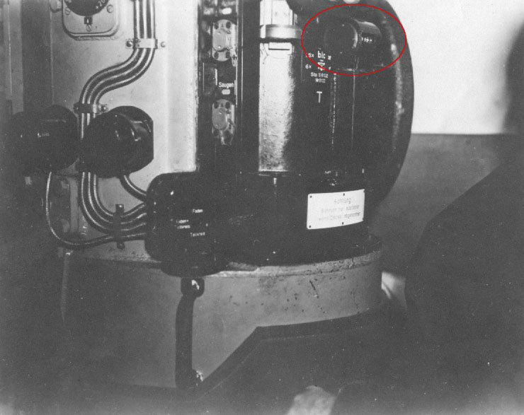
Photo 1. The type StaS C/2 periscope with the gear showing the true bearing visible [4]
The procedure was as follows: the periscope was set in such way, that one of the vertical lines of graticule was in the front of the target bow. Then the time interval between passing the target bow and target stern through this line was measured. In the same time, the other person (not one looking through the periscope) observed the true bearing counter and, if required, by means of the hand-wheel trained the periscope to keep the same value (i.e. true bearing) when the boat changed course (due to yaw or intentional course change).
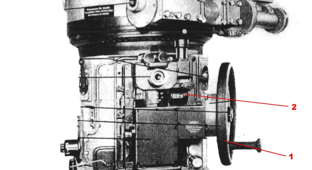
Photo 2. Type StaS C/2 periscope with hand-wheel for training (1) and true bearing counter (2) [5]
References:
[1] Thomas Müller, Analogrechner auf deutschen U-Booten des Zweiten Weltkrieges
[2] Submarine Periscope Type 2, 1940
[3] Tabellenheft zur Torpedo-Schießvorschrift für U-Boote, 1940
[4] Photographs taken during inspection by U.S. Naval Officers - Enclosure C of ONI Report
[5] Fritz Köhl, Axel Niestle, Vom Original Zum Modell - U-Boot Typ VIIC