
")
Torpedo calculator T. Vh. Re. S3
The heart of the torpedo fire control system was the torpedo calculator designated T. Vh. Re. S3, manufactured by the Siemens Company. It was an electro-mechanical device that was designed for solving two problems:
- Calculating the deflection angle β and converting its value into the gyro angle ρ (taking into account the parallax correction δ, resulting from the different location of the torpedo aiming device and torpedo tube, as well as the correction resulting from the torpedo turn after leaving the tube);
- Calculating the torpedo salvo spread angle ψ.
The development of this calculator started around the year 1939. In 1941 it was (together with the whole torpedo fire control system) delivered to the Kriegsmarine for testing. In the same year – after successfully passing all tests – the newly manufactured calculators were fitted in the front-going U-Boats.
From 1941 when the calculator entered service, till the end of the war, there were some modifications to its construction.
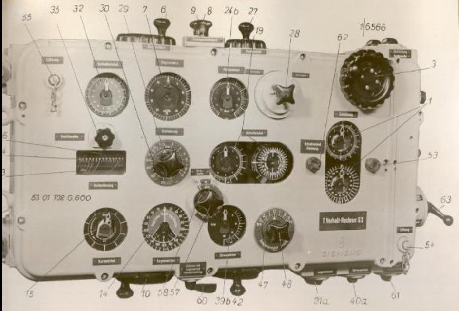
Photo 1. The torpedo calculator T. Vh. Re. S3 – early version – view of the front cover
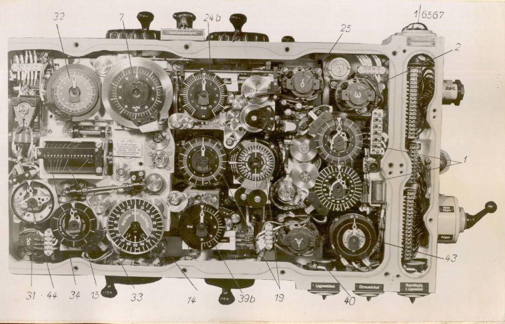
Photo 2. The torpedo calculator T. Vh. Re. S3 – early version – view after removing front cover
The calculator was enclosed in a steel casing, about 106 cm x 45 cm x 13 cm. It was located in the conning towers of the U-Boats (except the type II U-Boats - due to lack of space in the conning tower, it was installed in the control room) – on the starboard side in the case of type VII boats and on the port side in the case of type IX and XXI boats. On the type VII U-Boats it was installed horizontally, while on the type II, IX and XXI U-Boats – vertically.
In the standard operating mode, after entering the target data by means of the knobs, the calculator (taking into account the current target bearing transmitted from the periscope/UZO and own course received from the gyro-compass) automatically calculated the torpedo triangle solution and the torpedo salvo spread angle. In case of damage to some of the calculator's components or failure of the electrical systems, it was possible to operate the calculator in the manual mode.
The torpedo calculator consisted of the following components:
- component for solving the torpedo triangle;
- component for calculating the parallax correction;
- component for calculating the gyro angle;
- component for calculating maximum distance to target at the moment of the torpedo launch;
- component for calculating the torpedo salvo spread angle;
- component for entering the target bearing;
- component for calculating the current angle on the bow;
- component for calculating the current target bearing;

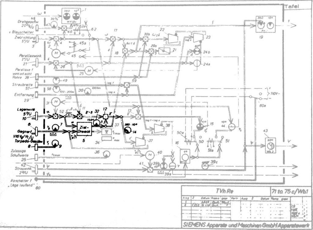
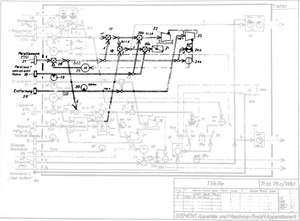
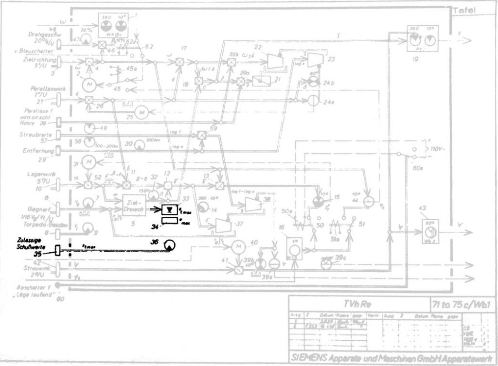
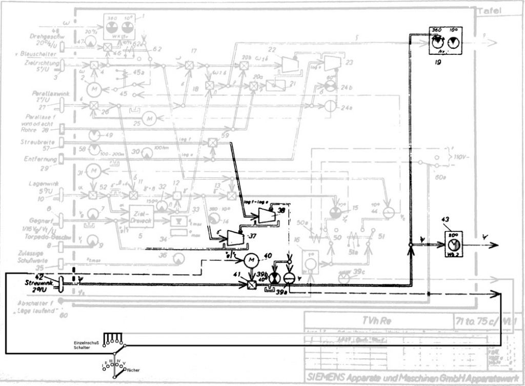
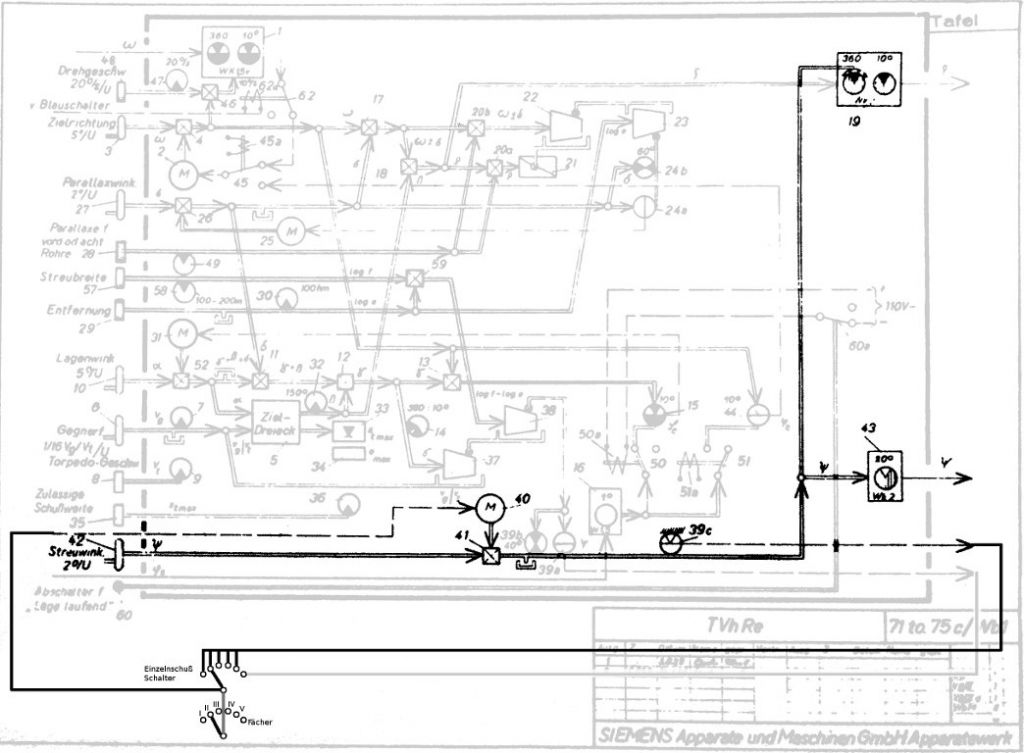
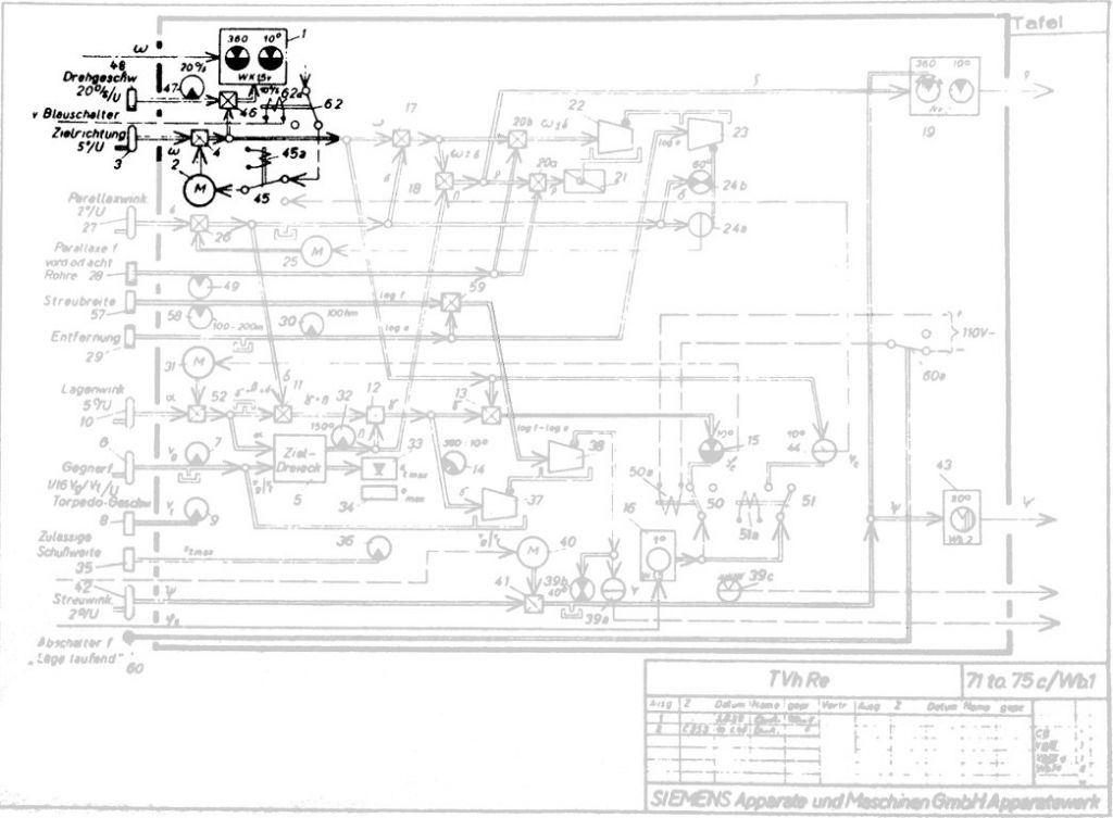
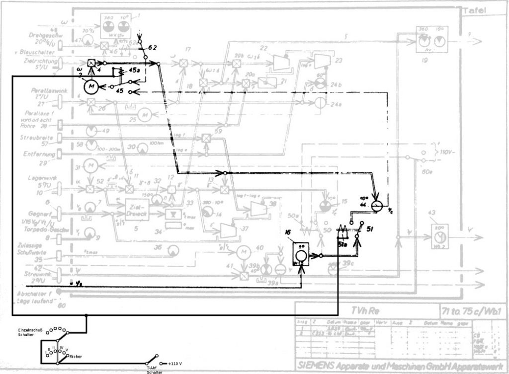
Drawing 1. The diagram of the torpedo calculator T. Vh. Re. S3 – valid on 1940 [1]
Description of the component for solving the torpedo triangle:
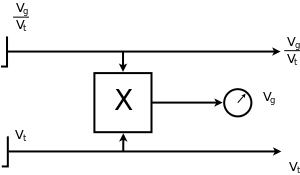
The component for solving the torpedo triangle calculated the deflection angle β from the following values: torpedo impact angle α and the quotient of the target and torpedo speed \(\frac{v_{g}}{v_{t}} \). Additional output from this component was used for calculating the maximum distance to the target emax at the moment of the torpedo launch.
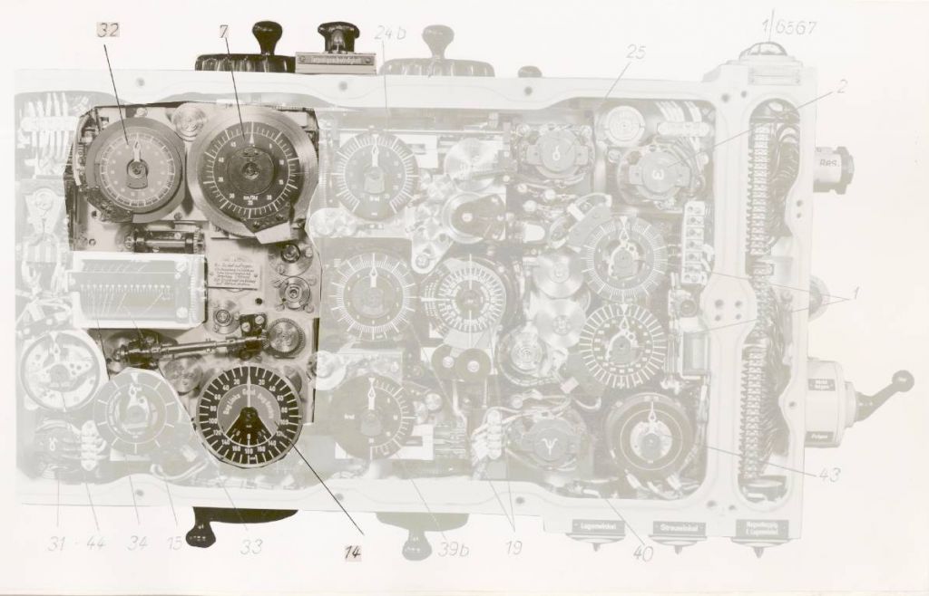
Photo 3. Component for solving the torpedo triangle – the view after removing the front cover
(7) target speed dial, (14) angle on the bow dial, (32) deflection angle dial
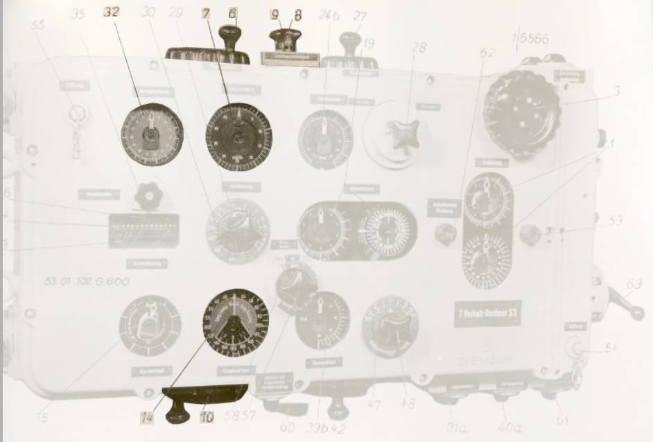
Photo 4. Component for solving the torpedo triangle – view of the front cover
(6) target speed knob, (7) target speed dial, (8) torpedo speed knob,
(9) torpedo speed indicator, (14) angle on the bow dial, (32) deflection angle dial
The torpedo speed vt and quotient of the target and torpedo speed \(\frac{v_{g}}{v_{t}} \) was entered by means of the knobs.
In the early versions of the calculator, the torpedo speed knob could be set only in three positions (30, 40, or 44 knots – the speed of the steam torpedoes G7a then in service could be set to these values, while the electric torpedoes G7e could cruise only at the speed of 30 knots). The quotient \(\frac{v_{g}}{v_{t}} \) and the torpedo speed vt were given as inputs of the multiplier unit (rack type), which calculated the target speed vg indicated by the dial. After setting the desired torpedo speed, the operator turned the knob responsible for setting the quotient of the target and torpedo speed, to make the pointer of the target speed dial show the correct value.
Thereby, instead of using the complex dividing unit for calculating the quotient, the much simpler multiplier unit could be used.
In the later version of the calculator, the target and torpedo speed were shown by the compound dial. The torpedo speed could be set to any value in the range 10 to 46 knots. This was due to adjusting the calculator’s construction for usage with the LUT and acoustic G7e torpedoes.

Photo 5. Knobs and dials of the target and torpedo speed in the early version of the calculator

Photo 6. Knobs and dials of the target and torpedo speed in the later version of the calculator
Drawing 2. The principle of calculating the quotient \(\frac{v_{g}}{v_{t}} \) in the early version of the calculator
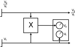
Drawing 3. The principle of calculating the quotient \(\frac{v_{g}}{v_{t}} \) in the later version of the calculator
The angle on the bow was entered indirectly – the torpedo impact angle α was entered by means of the knob and then was passed to the component for solving the torpedo triangle. The torpedo impact angle α was simultaneously added to the deflection angle β (calculated from the current torpedo impact angle α and the quotient of the target and torpedo speed \(\frac{v_{g}}{v_{t}} \)) resulting finally in the calculated angle on the bow γ being shown on the angle on the bow dial (the calculation was based on the principle that that the sum of the three angles in the triangle: α , β and γ is constant and equal to 180°).
Drawing 4. Component for solving the torpedo triangle [1]
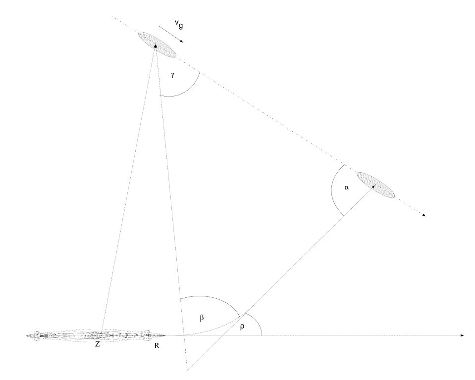
The component for solving the torpedo triangle calculated the deflection angle β – that is angle between the target bearing line and torpedo course. This angle was shown on the dial (with the scale in the range of 150°, but the dial was divided into two parts: 75° for port and 75° for starboard).
It should be noted, that in the torpedo calculator from U 995, this dial is fitted with a scale in the range of 360°, (divided into two parts: 180° for port and starboard). This is because in later versions of the calculator, the presentation of the deflection angle (Germ. Vorhaltwinkel) was abandoned. The impact angle (Germ. Schneidungswinkel) was presented instead.
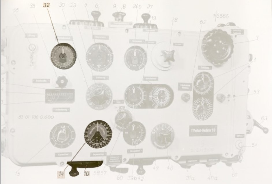
Photo 7. The knob (10) and dial (14) of the angle on the bow and dial (32) showing the deflection angle
The torpedo triangle looks as on the drawing below:
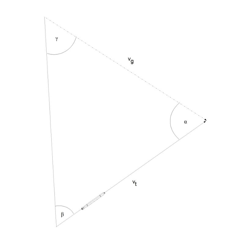
Drawing 5. Torpedo triangle
The law of sines applied to this triangle looks as follows:
\[\begin{aligned} \frac{v_{t}}{sin γ} = \frac{v_{g}}{sin β} \end{aligned} \]
that is
\[\begin{aligned} sin β = sin γ * \frac{v_{g}}{v_{t}} \end{aligned} \]
Because the component receives the quotient of the target and torpedo speed, the following substitution can be made:
\[\begin{aligned} u = \frac{v_{g}}{v_{t}} \end{aligned} \]
which results in:
\[\begin{aligned} sin β = u * sin γ \end{aligned} \]
Because in the triangle the sum of all angles is always equal to 180°, it can be noted:
\[\begin{aligned} γ = 180° - (α + β) \end{aligned} \]
That is (due to the periodical feature of the sines function)
\[\begin{aligned} sin γ = sin (α + β) \end{aligned} \]
So we get:
\[\begin{aligned} sin β = u * sin (α + β) \end{aligned}\]
which can be transformed to the final result:
\[\begin{aligned} ctg β = \frac{1}{u * sin α} – ctg α \end{aligned} \]
That means, that deflection angle β is calculated after entering the quotient of the target and torpedo speed and torpedo impact angle:
\[\begin{aligned} β = arc ctg (\frac{1}{u * sin α} – ctg α)\end{aligned}\]
The component for solving the torpedo triangle is (most likely) implemented as a set of 3‑dimensional cams and differential gears:
- 2-dimensional cam, implementing the function ctg α
- 3-dimensional cam implementing the function u * sin α
- 2-dimensional cam inverting the function u * sin α
- differential gear performing the subtraction
- 2-dimensional cam implementing function arc ctg
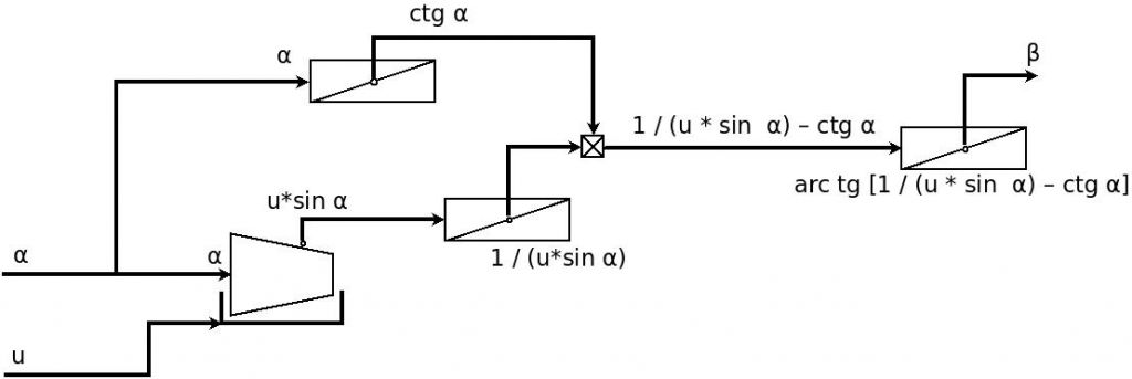
Drawing 6. Presumed implementation of the component for solving the torpedo triangle
Description of the component for calculating the parallax correction:
The component for solving the torpedo triangle mathematically models the ideal situation, when the torpedo aiming device is located at the same place as the torpedo tube, and the torpedo after leaving the tube runs a straight course.
In the case of the U-Boat this is not true – the aiming device is located some distance from the torpedo tubes (on type VII U-Boats this distance is ~28 meters). That means, that the target bearing taken at the torpedo tube is different from the bearing taken at the aiming device. Likewise the angle on the bow – observed from the torpedo tube is different than the one observed at the aiming device.
Drawing 7. The difference in the target bearings and angles on the bow observed at the torpedo tubes and at the aiming device
Moreover, when the torpedo turns after leaving the tube, it runs on a track that is parallel to the line which connects the torpedo tube with the impact angle. This actual track is displaced by the value which depends on the turn angle (gyro angle ρ).
Drawing 8. The displacement of the torpedo track resulting from the torpedo turn
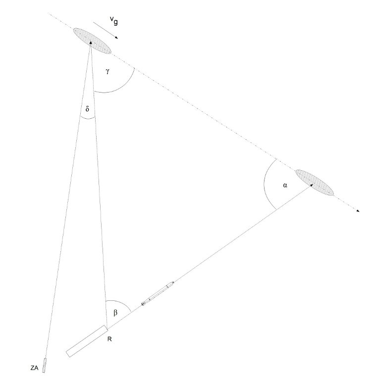
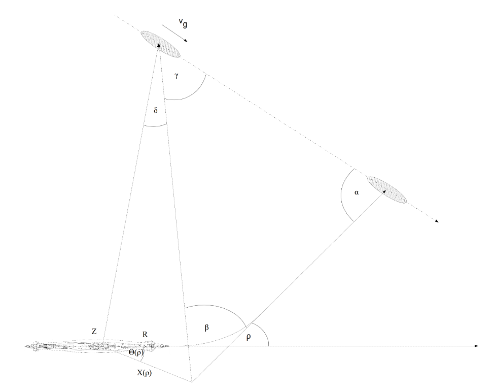
These two effects require taking into account some correction while solving the torpedo triangle. This correction is called the parallax correction δ (Germ. Winkelparalaxverbesserung). The torpedo triangle with the parallax correction is based on the so called equivalent point of fire (Germ. ideeller Torpedoeintrittsort).
Drawing 9. The torpedo triangle based on the equivalent point of fire
The equivalent point of fire was located at the prolongation of the torpedo track, at a distance equal to the sum of the initial straight torpedo run and the length of the arc, from the point A where the turn ended. In other words, the length of the section E1A is equal to the length of the section EA. The concept of the equivalent point of fire results from the fact that the distance between this point and the point where the turn ended is the same as the distance between the torpedo tube and the point where the turn ended. That means, that both segments can be traveled by the torpedo in the same time. The location of the equivalent point of fire E1 depends on the gyro angle ρ.
In the general case, the parallax correction δ depends on three variables: target bearing ω, distance to the target E at the moment of torpedo launch and the gyro angle ρ:
δ = f(ρ, ω, E)
To solve the torpedo triangle based on the equivalent point of fire the angle on the bow γ1 (as observed from the equivalent point of fire), is used which is the angle on the bow γ1 (as observed from the aiming device) modified with the parallax correction δ:
γ = γ1 + δ
In other words, the angle on the bow γ1 is the angle observed from the equivalent point of fire, and the difference between the angles observed from the equivalent point of fire and the aiming device is the parallax correction.
The parallax correction δ is entered into the component for solving the torpedo triangle indirectly.
The angle on the bow γ1 (as observed at the aiming device) is visible on the dial and is strictly dependent on the angles α and β (where the angle β is in turn dependent along with the others on the angle α). As mentioned before, the angle on the bow is calculated as the sum of the deflection angle β (which depends on the angle α) and torpedo impact angle α. To this sum the additional component parallax correction δ is introduced – so the sum of the angles (that is angle on the bow γ1 as observed from the aiming device) is changed by the value δ. To adjust the value of the angle on the bow to the real value, the operator turns the knob of the torpedo impact angle by small amounts, changing slightly the deflection angle β. The deflection angle was added to the parallax correction δ and impact angle α, resulting in the angle on the bow γ1 (as observed from the aiming device) – but calculated with the parallax correction taken into account (this correction was taken into account by changing the impact angle).

Drawing 10. The component for solving the torpedo triangle with parallax correction taken into account [1]
Of course, the parallax correction depends (as mentioned before) on (among others) the gyro angle ρ, which in turn depends on the deflection angle β. In connection with the fact that to calculate the deflection angle parallax correction is needed, it is obvious that the solution of this problem requires solving a system of two (implicit) equations. This complex mathematical problem resulted in the firing of gyro-angled torpedoes becoming common after developing the suitable calculating devices (by the German, Japanese, and American navies). On the other hand, in the navies which did not acquire such devices (among others the British, Polish and Russian Navies) – despite having the technical possibility of launching gyro-angle torpedoes – the straight-runners were used (without gyro angle).
Calculating the parallax correction δ was done based on the location of the equivalent point of fire. The Cartesian coordinates of this point (relative to the aiming device) depend on the gyro angle ρ and can be easily determined analytically. There is only the need to know the length of the torpedo initial straight run, torpedo turn radius (for German torpedoes G7a and G7e these values were 9.5 m and 95 m respectively) and the distance between the torpedo tube and the aiming device (in the case of type VIIC U-Boats this was ~27 m). These coordinates can be expressed by the following formulas (for gyro angle in the range 0-90°):
x0 = 27 + 9,5 + 95 * sin ρ – (ρ * 95 + 9,5) * cos ρ
y0 = 95 * (1 - cos ρ) – (ρ * 95 + 9,5) * sin ρ
(the angle ρ not being the argument of the trigonometric function has to be given in radians)
Drawing 11. The location of the equivalent point of fire for the gyro angle ρ in the range 0-90°
For the given value of the gyro angle ρ, the location of the equivalent point of fire in relation to the aiming device can be expressed by polar coordinates: X(ρ) – distance between the aiming device and the equivalent point of fire, θ(ρ) – angle between the diametrical line of the U-Boats and the line connecting the aiming device and equivalent point of fire.
Drawing 12. The polar coordinates of the equivalent point of fire
The polar coordinates X(ρ) and θ(ρ) can be expressed by the Cartesian coordinates:
\[\begin{aligned} X(ρ) = \sqrt[2]{{x_{0}}^2 + {y_{0}}^2} \end{aligned}\]
\[\begin{aligned} tg θ(ρ) = \frac{y_{0}}{x_{0}} \end{aligned}\]
that is:
\[\begin{aligned} θ(ρ) = arc tg\frac{y_{0}}{x_{0}} \end{aligned}\]
Applying the law of sines to the triangle presented on the drawing below, we get:
\[\begin{aligned} \frac{sin (ω + θ(ρ) + δ)}{E} = \frac{sin δ}{X(ρ)} \end{aligned}\]
where E means the distance to the target at the moment of torpedo launch (measured from the aiming device).
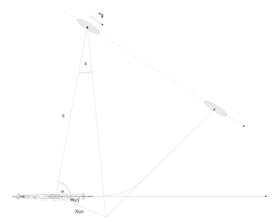
Drawing 13. The relationship between the parallax correction and the location of the equivalent point of fire
The formula above can be converted to the following:
\[\begin{aligned} sin δ = X(ρ) * \frac{sin (ω + δ + θ(ρ))}{E} \end{aligned}\]
Because in practice, the value of the parallax correction δ reaches a maximum of 25°, the following approximation can be done:
\[\begin{aligned} sin δ = δ \end{aligned}\]
(for the angles in the range 0 – 25°, the sinus of this angle is approximately equal to this angle expressed in radians).
So finally we get:
\[\begin{aligned} δ = X(ρ) * \frac{sin (ω + δ + θ(ρ))}{E} \end{aligned}\]
The solution to this implicit equation is determined by the component for calculating the parallax correction.
 Drawing 14. The component for calculating the parallax correction [1]
From the above diagram it seems that the component for calculating the parallax correction consists of one 2-dimensional cam, two 3-dimensional cams and a comparator (which controls the electric motor), that is integrated with the compound dial.
The exact implementation of this component is not known, but it seems, that the 2-dimensional cam (whose input value is the gyro angle) is a double cam that generates a pair of output values – the polar coordinates of the equivalent point of fire (its function can be interpreted as a table of pre-calculated values).
The first 3-dimensional cam indicated on the diagram is – most likely - a set of two 3-dimensional cams, one of them receives values (ω + δ) and θ(ρ) and generates the value sin (ω + δ + θ(ρ)), while the other – receiving the output value of the first cam and value X(ρ) implements the function:
\[\begin{aligned}g(ρ, ω + δ) = X(ρ) * sin (ω + δ + θ(ρ))\end{aligned}\]
The second 3-dimensional cam indicated on the diagram receives as input the value generated by the first 3-dimensional cam (or most likely by a set of two cams, as described before) and the logarithm of the distance to the target. This cam implements the function:
\[\begin{aligned} h(g(ρ, ω + δ), E) = \frac{g(ρ, ω + δ)}{E}\end{aligned}\]
that is:
\[\begin{aligned} h(ρ, ω + δ, E) = X(ρ) * \frac{sin (ω + δ + θ(ρ))}{E}\end{aligned}\]
The output value h(ρ, ω + δ, E) is compared by the comparator with the value δ (the same which is received by the first 3-dimensional cam) and the following equation is implemented:
\[\begin{aligned} δ = X(ρ) * \frac{sin (ω + δ + θ(ρ))}{E} \end{aligned}\]
which was the basis of our consideration of the operating principle of the component for calculating the parallax correction.
The error signal generated by the comparator controls the electric motor that turns the shaft responsible for setting the value of the parallax correction δ. The whole component in the feed-back loop tries to equalize the left and right side of the equation – that is tries to solve it.
The current value of the left and right side of the equation is shown at the compound dial (one pointer rotating around the dial edge and second dial rotating around the center axis).
In case of damage to the electrical subsystems of the calculator, manual operation is possible by means of the knob coupled (through the differential gear) with the shaft responsible for setting the parallax correction δ. In such a case, the operator observers the pointers at the dial and by turning the knob, tries to match their positions.

Photo 8. The knob (27) and dial (24b) of the parallax correction and parallax switch (28)
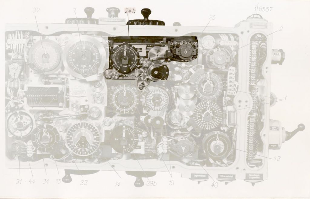
Photo 9. The component for calculating the parallax correction
(24b) parallax correction dial, (25) motor of the component for calculating the parallax correction
It should be noted that one of the input values for the second 3-dimensional cam is the logarithm of the distance E to the target. This logarithm is the side effect of the simplification of the calculator in some other place – the component for calculating the torpedo salvo spread angle. In that component – instead dividing two values – the difference of two logarithms was used. That's why the logarithm of the distance to the target is passed to the component for calculating the parallax correction. Again – it is not clear how it is implemented – most likely the function implemented by the second 3-dimensional cam is compound also from the exponential function (that is inverse function to the logarithm) to get plain distance.
For any gyro angles entered in the torpedo loaded into stern tube, the Cartesian coordinate x0 of the equivalent point of fire is negative. That means, that polar coordinate θ(ρ) has the opposite sign relative to the value for the same gyro angle set on the bow tubes. To keep the calculations correct, the sign of the calculated parallax correction δ has to be reversed. It was done by means an additional pair of gears with the ratio 1:-1, which were coupled into the circuit by means of the parallax switch (Parallax Vorn/Acht). This switch had to be set in the correct position depending on the torpedo tubes used (bow or stern).
Description of the component for calculating the gyro angle:
The deflection angle β calculated by the component for solving the torpedo triangle is the angle between the target bearing line (at the moment of torpedo launch) and the torpedo track. To launch the torpedo according to the calculated deflection angle, the torpedo tube had to be aimed (by training the tube in the case of trainable tubes or by maneuvering the vessel in the case of fixed tubes) so that the angle between the longitudinal line of the tube and the target bearing line at the moment of firing was equal to the deflection angle β. After torpedoes that were able to turn (after leaving the tube) by the previously set angle (gyro angle) entered service, aiming with the tube or maneuvering the vessel became unnecessary.

Drawing 15. The torpedo triangle for a straight torpedo shot and for a torpedo launch with a gyro angle
The gyro gear of the torpedo had to be set to the gyro angle ρ, which is equal to the sum of the deflection angle β and the target bearing ω1 as observed from the equivalent point of fire.
ρ = ω1 - β
As can be seen on the drawing below, the target bearing as observed from the equivalent point of fire is equal to the target bearing as observed from the aiming device, but modified by the value of the parallax correction δ.

Drawing 16. The relation between the target bearings observed from the equivalent point of fire and from the aiming device
So, the gyro angle can be expressed as follow:
ρ = ω + δ - β
The gyro angle is calculated by the component for calculation the gyro angle, which consists of two differential gears and one doubled dial coupled with a selsyn transmitter.
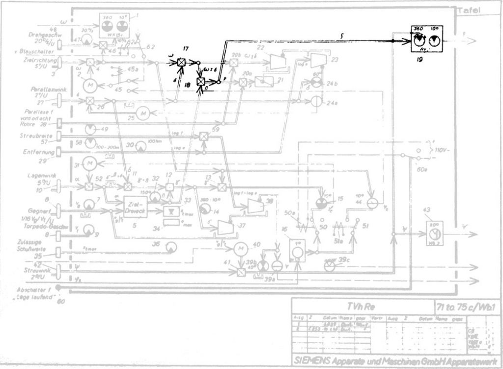
Drawing 17. The component for calculating the gyro angle [1]
The gyro angle dial presents (using two dials) the calculated gyro angle. One dial showed the angle in the range 0 - 360°, the second – in the range 0 – 10°. The gyro angle was shown as the angle measured relative to the longitudinal line of the U-Boat. The selsyn transmitters coupled with the dials transmitted the value of the gyro angle to the gyro angle receivers, which were located in the torpedo tubes.
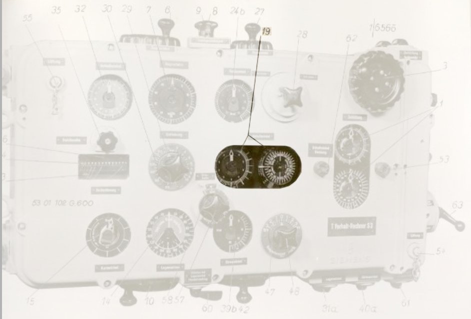
Photo 10. Double gyro angle dial
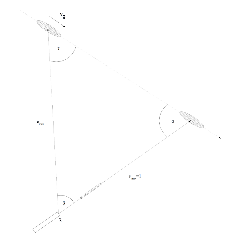
Description of the component for calculating maximum distance to target at the moment of the torpedo launch:
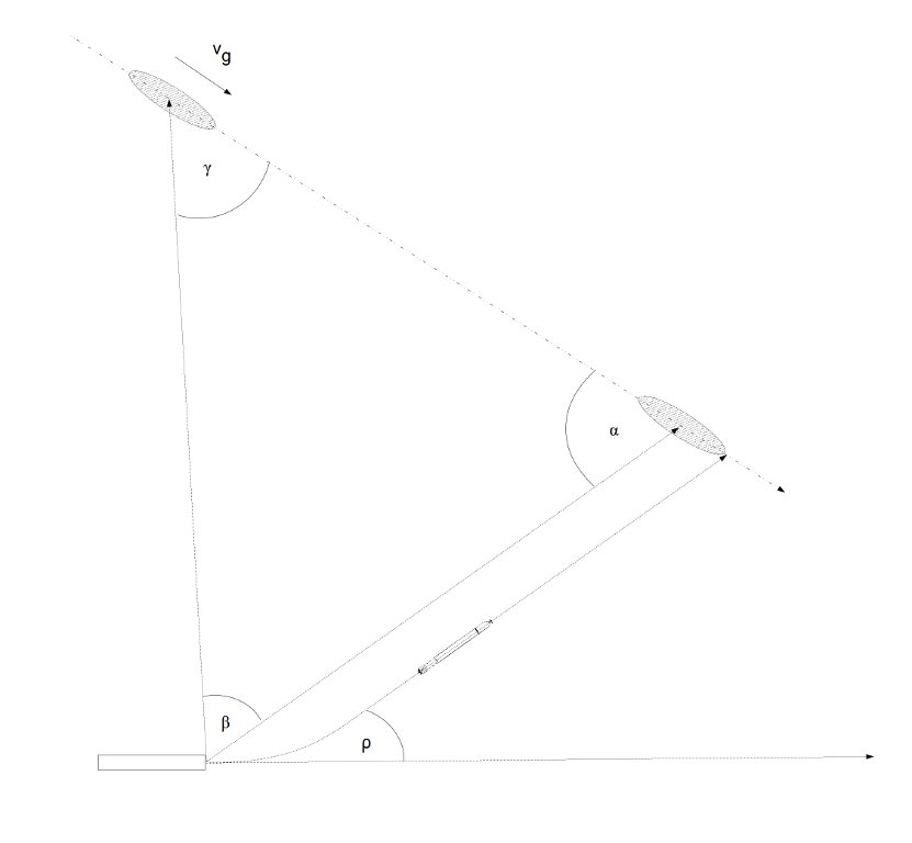
The component for solving the torpedo triangle also made possible calculating the maximum permissible distance to the target emax (Germ. Reichentfernung) at the moment of torpedo launch for a given length of the torpedo run st max (Germ. Reichweite).
Drawing 18. Torpedo triangle based on the maximum permissible distance to the target emax and length of the torpedo run st max
Thereby, knowing the maximum length of the torpedo run, the torpedo officer could know if the distance to the target at the moment of the torpedo launch is within the torpedoes’ range.
Photo 11. The component for calculating maximum distance to the target
(33) drum showing the maximum length of the torpedo run,
(34) the lineal with a scale for reading the maximum permissible distance to the target at the moment of the torpedo launch
Photo 12. Indicators and knobs of the component for calculating maximum distance to the target
(33) drum showing the maximum length of the torpedo run
(34) the lineal with the scale for reading the maximum permissible distance to the target at the moment of the torpedo launch
(35) the maximum length of the torpedo run knob, (36) the maximum length of the torpedo run indicator
The indicator showing the maximum distance to the target is in the form of a trainable drum (st max) with a horizontal axis of rotation and a horizontal ruler (emax) with a scale in the range from 10 to 140 hm. Lines labeled with values from 10 to 140 hm are drawn on the lateral surface of the drum.
Furthermore, the knob coupled with the dial is located over the drum. This knob is used for entering the maximum length of the torpedo run (Germ. Zulassige Schußweite, which for the steam torpedoes was equal to – depending on the speed - 12500, 8000 and 6000 meters, whereas for electric torpedoes – depending on the version - 5000 and 7500 meters).
Photo 13. The knob for setting the maximum length of the torpedo run
The component for solving the torpedo triangle, besides calculating the deflection angle β, also calculates the distance to the target for the unitary maximum torpedo run length (that is for a maximum torpedo run length of 1).
Drawing 19. The torpedo triangle based on the unitary maximum torpedo run length st max=1
Due to a lack of information about the internal construction of the component for solving the torpedo triangle, it is hard to determine for sure, how this calculation was performed. Most likely the following formula was used (which used the sines law)
\[\begin{aligned} \frac{e}{sin α} = \frac{s_{t}}{sin (α + β)} \end{aligned}\]
that is (for unitary st)
\[\begin{aligned} e = \frac{sin α}{sin (α + β)} \end{aligned}\]
This function can be implemented as a 3-dimensional cam and a differential gear. The distance to the target e (for unitary maximum length of the torpedo run) is led outside the component by means of the shaft that drove the drum.
Several lines are drawn on the lateral surface of the drum. After unreeling the lateral surface to the plane, we get the following drawing:
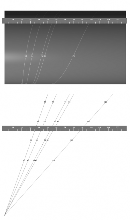
Drawing 20. The drum and the unreeled lateral surface of the drum
After unreeling the lateral surface – to make exanimating it easier – we rotate the drawing by 90°. Let's assume, that the drum is not rotating, but the ruler moves (that is the unreeled lateral surface does not move under the ruler), but the ruler moves over the unreeled surface to the right and to the left.
Drawing 21. The unreeled lateral surface of the drum after rotating it by 90°
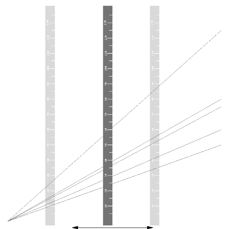
Because the rotation of the drum – or movement of the vertical ruler – corresponds to the distance to the target for unitary length of the torpedo run st max = 1, if we multiply this distance by any value of the maximum length of the torpedo run (let's say 5000 meters), we get the distance to the target not for unitary length of the torpedo run, but for the maximum length of the torpedo run equal to (i.e.) 5000 meters. It can be formally expressed as:
emax = e * st max
where st max is (i.e.) 5000 meters.
Lines are drawn on the lateral surface of the drum that are linear functions expressed by the formula above, but for different values st max. These lines are all passing the origin of the coordinate system and differ only by a tilt. The relation between the angle of the tilt α and the constant st max is as follows:
\[\begin{aligned}tg α = \frac{s_{t max}}{14000} \end{aligned}\]
On the drawing below, one line on the lateral side was featured (arbitrarily). This line corresponds to the constant st max = 7500 meters. The value emax is found by finding on the movable vertical ruler the point where the ruler crosses the line corresponding to the maximum length of the torpedo run (in this case: 7500 meters). The value read from the scale at the ruler associated with this cross-point is equal to the value of the function:
emax = e * st max
for the distance to the target e (calculated for the unitary maximum length of the torpedo run) calculated by the component for solving the torpedo triangle and the constant st max which corresponded to the maximum length of the run of the real torpedo.
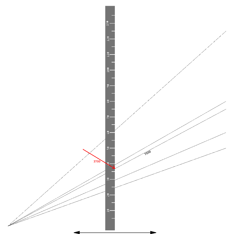
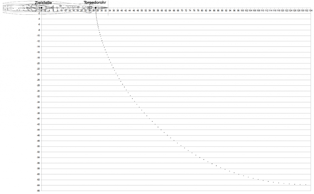
Drawing 22. The way of reading the maximum distance to the target (in this case ~3650 meters) at the moment of the torpedo launch for a torpedo with the maximum length of run equal to 7500 meters
The maximum length of the torpedo run is set by the knob at the beginning of the operation of the calculator. This initially set value relieves the operator from remembering this value and makes it possible to check it any time it is necessary. When the calculator is used during the attack with the torpedo salvo with torpedoes of various types (i.e. two steam torpedoes and two electric torpedoes), the entered value of the maximum length of the torpedo run is equal to the lower value.
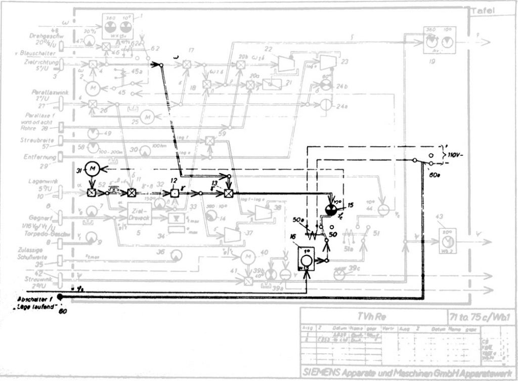
Drawing 23. The component for calculating the distance to the target at the moment of torpedo launch [1]
Description of the component for calculating the torpedo salvo spread angle:
When launching a torpedo salvo, each torpedo runs a slightly different course. Thereby the probability of hitting the target is increased, because several torpedoes cross the target course at several different points (thus compensating for errors in estimating target course parameters), not only at one point as in the case of a single shot.
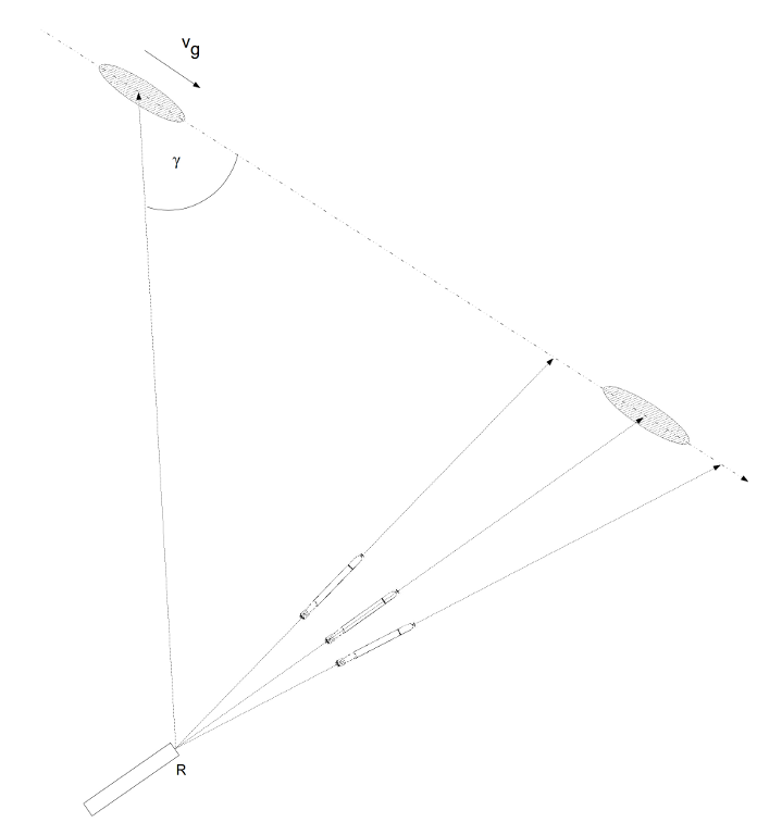
Drawing 24. Torpedo salvo
The gyro angle ρ for each torpedo in the salvo is calculated in the same way as in the case of a single shot, but additionally, the calculator evaluates the salvo spread angle ψ and that value is used to modify the gyro angles. These two values: gyro angle ρ and spread angle ψ are transmitted by means of selsyn links to the gyro angle receiver (Germ. Schußwinkelempfänger). In the gyro angle receiver, depending on the size of the salvo, the individual gyro angle for each was calculated. A description of the gyro angle receiver operation is available here.
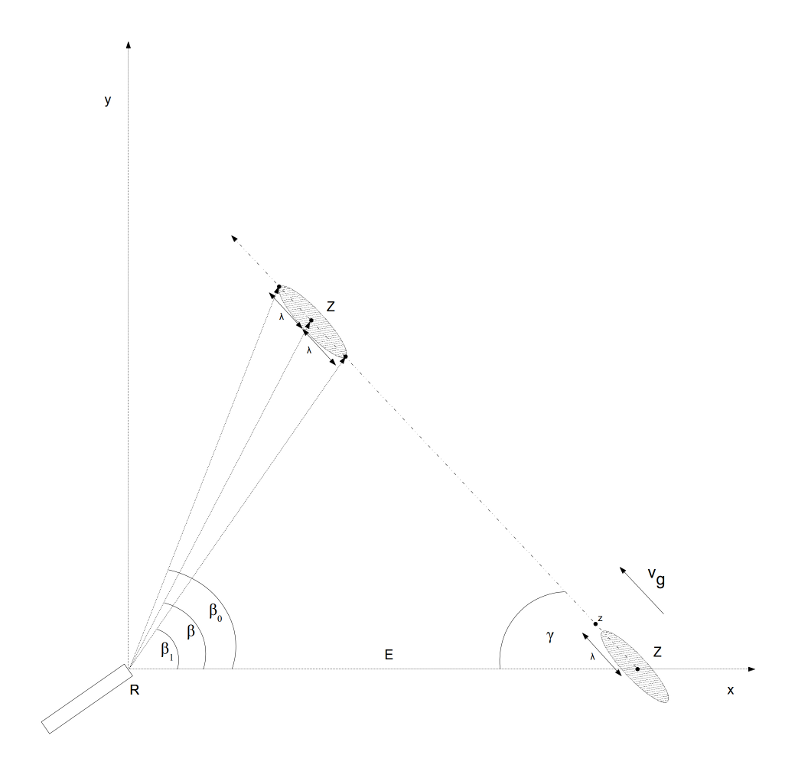
The torpedo salvo spread angle ψ depends on the distance to the target E, length of the target l, angle on the bow γ and quotient of the target and torpedo speed \(\frac{v_{g}}{v_{t}}\).
The spread angle is calculated in the following way. The drawing below presents the torpedo track, target course and target bearing line at the moment of the torpedo launch. The drawing is so oriented, that the target bearing line overlaps with the horizontal axis of the coordinates system.
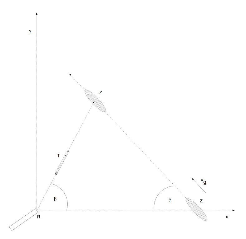
Drawing 25. Torpedo triangle
The coordinates describing the location of the torpedo T and the target Z depending on the time can be expressed by the following formulas:
T: \( \begin{cases} x = t * v_{t} * cos β \\ y = t * v_{t} * sin β \end{cases} \) Z: \( \begin{cases} x = E – t * v_{g} * cos γ \\ y = t * v_{g} * sin γ \end{cases} \)
where t – time, vt – torpedo speed, vg – target speed, β – deflection angle, γ – angle on the bow, E – distance to the target at the moment of the torpedo launch.
The coordinates of the point z, which is located relative to the point Z by the distance λ (but is located at the target course) can be expressed as follows:
z: \( \begin{cases}x = E – (t * v_{g} + λ) * cos γ \\ y = (t * v_{g} + λ) * sin γ\end{cases} \)
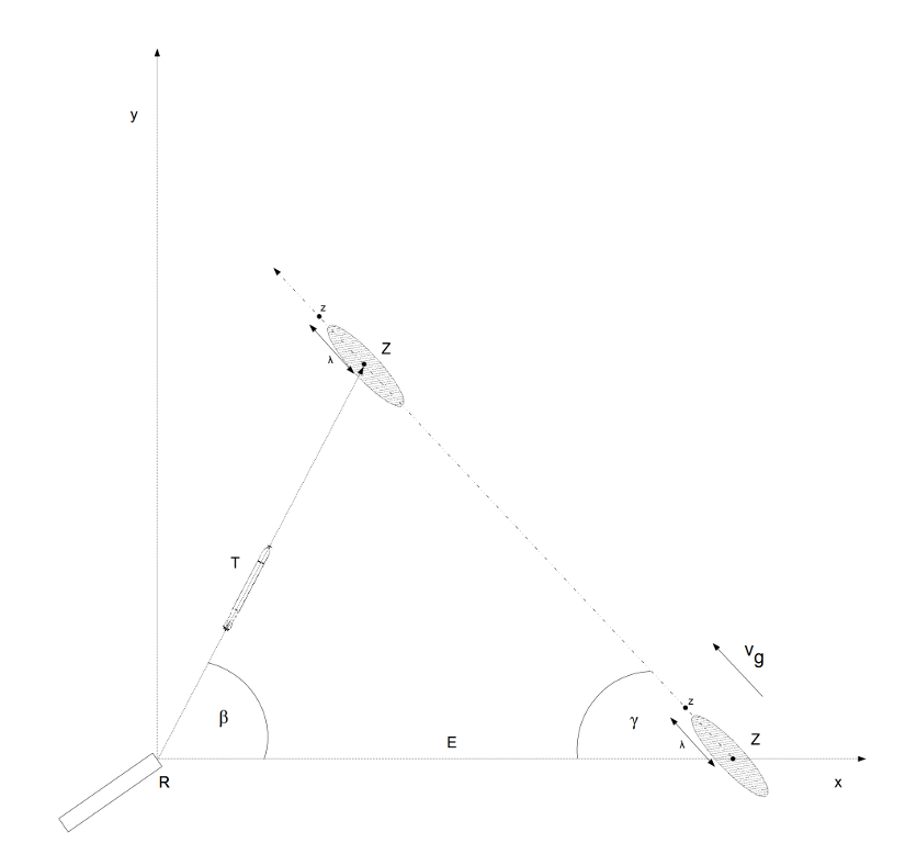
Drawing 26. Torpedo triangle with the point z
The coordinates of the bow and the stern of the target can therefore be defined by the pair of values λ = λ0 and λ = -λ1.
The square of the distance between the point T, where the torpedo is located and the point z can be expressed by the formula:
\[\begin{aligned}|Tz|^{2} = (x_{T} – x_{z})^{2} + (y_{T} – y_{z})^{2} \end{aligned}\]
The torpedo passes the point z (that is hit the target bow or stern), only when distance |Tz| is equal 0, that is:
\[\begin{aligned}0 = (x_{T} – x_{z})^{2} + (y_{T} – y_{z})^{2}\end{aligned}\]
This condition is true only when all the following formulas are true:
\((x_{T} – x_{z})^{2} = 0\) i \((y_{T} – y_{z})^{2} = 0 \)
that is
\[\begin{aligned}(t * v_{t} * cos β – E + (t * v_{g} + λ) * cos γ)^{2} = 0 \end{aligned}\]
and
\[\begin{aligned}(t * v_{t} * sin β – (t * v_{g} + λ) * sin γ)^2 = 0 \end{aligned}\]
The above equations can be transformed to designated value of time t:
\[\begin{aligned}t = \frac{E - λ * cos γ}{v_{t} * cos β + v_{g} * cos γ}\end{aligned}\]
and
\[\begin{aligned}t = \frac{λ * sin γ}{v_{t} * sin β – v_{g} * sin γ}\end{aligned}\]
and then they can be compared:
\[\begin{aligned}\frac{E - λ * cos γ}{v_{t} * cos β + v_{g} * cos γ} = \frac{λ * sin γ}{v_{t} * sin β – v_{g} * sin γ}\end{aligned}\]
If the following substitution is performed:
\(u = \frac{v_{g}}{v_{t}}\) oraz \(μ = \frac{λ}{E}\)
we get:
\[\begin{aligned}sin β – u * sin γ = μ * sin (β + γ) \end{aligned}\]
This is an implicit equation that allows calculating the deflection angle β for the angle on the bow γ, in such a way, that the torpedo hits the point z, which is located at distance λ from the middle of the target.

Drawing 27. Torpedo triangle with the torpedo hitting the point z
It should be noted that when value λ is 0 (that is when we want the torpedo hitting in the middle of the target), the equation looks like following:
\[\begin{aligned}sin β – u * sin γ = 0\end{aligned}\]
Knowing that:
\[\begin{aligned}u = \frac{v_{g}}{v_{t}}\end{aligned}\]
we can see, that this is the law of sines applied to the torpedo triangle.
For convenience, instead of considering the location of the stern and bow of the target as the points distanced from the middle of target by value λ, the following substitution can be made:
\[\begin{aligned}μ_{0} = \frac{l}{2*E}\end{aligned}\]
where l is the length of the target.
To make a three-torpedo salvo hitting the bow, middle and stern of the target, each torpedo has to be launched with the deflection angle β0, β and β1 respectively, where each of these values meets one of the following equations:
\[\begin{cases}sin β_{0} – u * sin γ = μ_{0} * sin (β_{0} + γ) \\ sin β – u * sin γ = 0 \\ sin β_{1} – u * sin γ = - μ_{0} * sin (β_{1} + γ)\end{cases}\]
Drawing 28. Torpedo triangle for a salvo
Because, in practice, in most cases the target (with a length up to 150 meters – i.e. Liberty type cargo ships: ~135 meters, T2 type tankers: ~152 meters) were attacked from a minimum distance of 500 meters, the value μ0 is rather small (μ0 < 0.15). That means that the angle between the courses of torpedoes aimed at the target’s bow and stern (that is angle β1 - β0) is a maximum ~20°. Knowing the fact, that for the angles α in the range 0 – 20°, the sin α ~ α and cos α ~ 1, all three equations above can be transformed to the form:
\[\begin{cases}sin β – u * sin γ = μ_{0} * sin (β + γ) – (β_{0} - β) * cos β \\ sin β – u * sin γ = 0 \\ sin β – u * sin γ = - μ_{0} * sin (β + γ) – (β_{1} - β) * cos β\end{cases}\]
After inserting the second equation into the two others, we receive two formulas:
\[\begin{cases}β_{0} - β = \frac{μ_{0} * sin (β + γ)}{cos β} \\ β_{1} - β = - \frac{μ_{0} * sin (β + γ)}{cos β}\end{cases}\]
So the salvo spread angle ψ (being the difference β1 – β0) can be calculated using the following formula:
\[\begin{aligned}ψ = \frac{2 * μ_{0} * sin (β + γ)}{cos β}\end{aligned}\]
This formula can be transformed to the following:
\[\begin{aligned}ψ = \frac{l}{E} * sin γ * (1 + \frac{cos γ}{\sqrt[2]{\frac{v_{t}}{v_{g}}^{2}-sin^{2}γ}})\end{aligned}\]
where the spread angle depends on the angle on the bow γ, length of the target l, distance to the target E at the moment of launch and quotient of the torpedo and target speed \(\frac{v_{t}}{v_{g}}\).
This formula is much more complicated, but its advantage is that there is no need to use the values that are calculated by other components of the calculator (deflection angle β). Most likely, the calculator designers wanted to make calculation of the spread angle possible even if the component for solving the torpedo triangle is damaged.
This formula was implemented using two 3-dimensional cams and differential gears.
 Drawing 29. Component for calculating the torpedo salvo spread angle [1]
The first 3-dimensional cam receives as inputs the quotient of the target and torpedo speed \(\frac{v_{g}}{v_{t}}\) and the angle on the bow γ.
As mentioned before (in the description of the component for calculating the parallax correction), the distance to the target is entered in the calculator as a logarithmical value. The target length was entered in a similar way. Thus, calculating the quotient \(\frac{l}{E}\) was performed by the differential gear subtracting these values. The logarithmical value of this quotient is fed (together with the output value of the first 3-dimensional cam) to the inputs of the second 3-dimensional cam. Its output value is the salvo spread angle ψ.
The salvo spread angle is shown on the dial which is scaled in the range of 0 to 20°. This dial is of the compound type – its inner pointer shows the output value of the cam, while the outer pointer (on the edge of dial) shows the value represented by the shaft being rotated by electric motor. The electric motor is controlled by the error signal, which results from the relative position of both pointers – that is the electric motor rotates the shaft in such way as to match the positions of both pointers. This shaft also drives the selsyn transmitter, which transmits the value of the spread angle to the gyro angle receiver.
In case of damage to the electrical subsystem or the electric motor, the component can be operated manually (through the differential gear) by means of the knob.
Moreover after disconnecting the electric motor it is possible to enter an arbitrary value of the salvo spread by means of the knob.
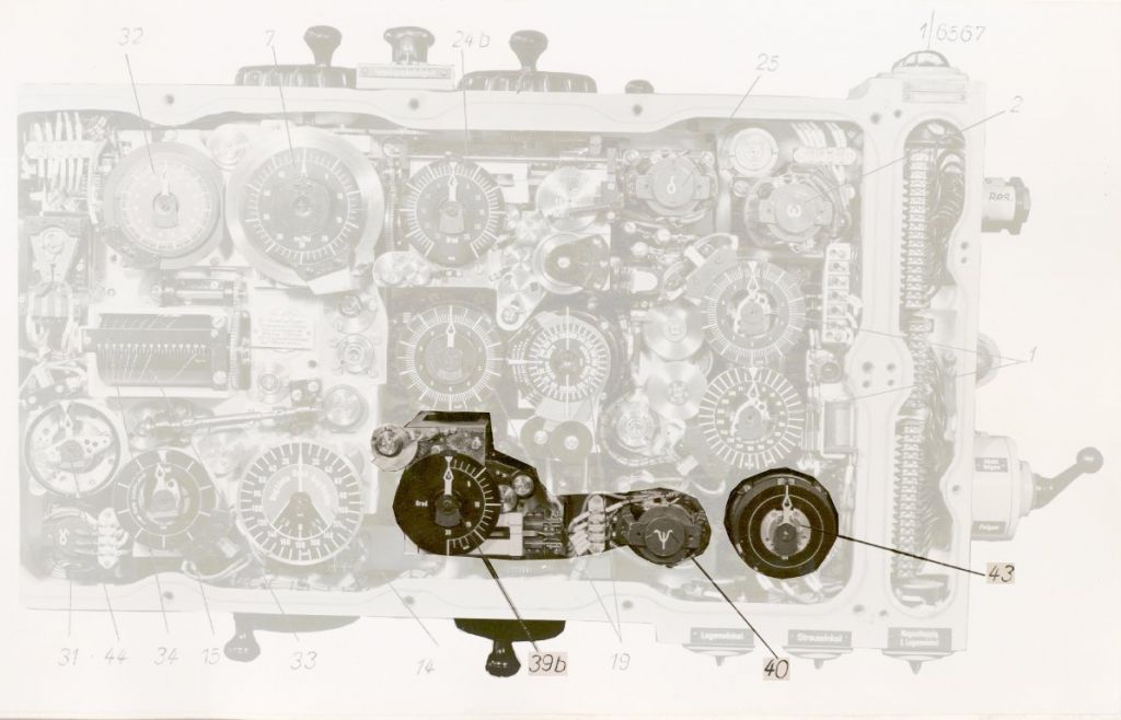
Photo 14. Component for calculating the torpedo salvo spread angle
(39b) torpedo salvo spread angle dial
(40) motor of the component for calculating the torpedo salvo spread angle
(43) selsyn transmitter for the torpedo salvo spread angle
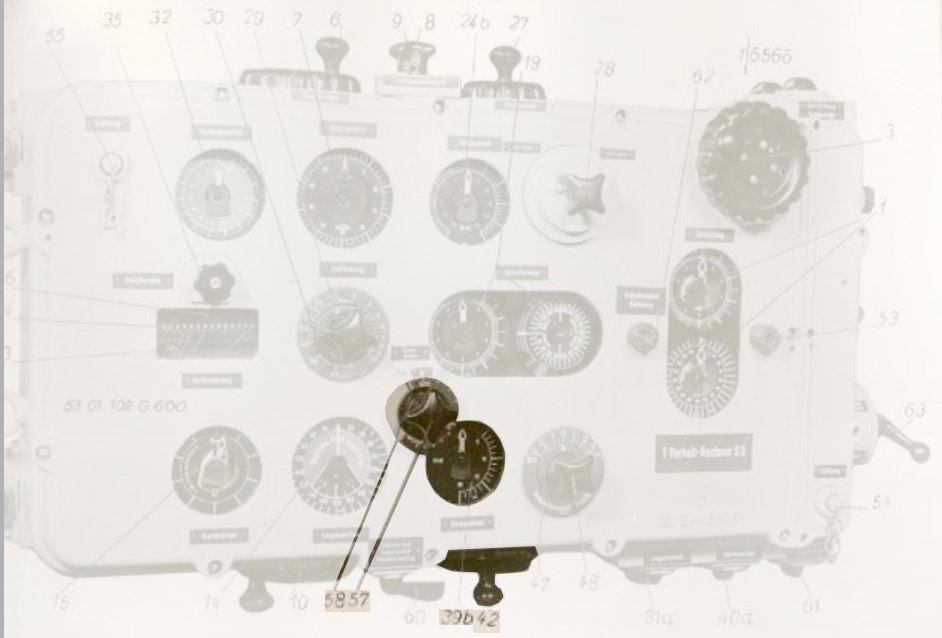
Photo 15. The dials and knobs of the component for calculating the torpedo spread angle
(39b) torpedo salvo spread angle dial
(42) torpedo salvo spread angle knob
(57) target length knob
(58) target length indicator
The so called “zero-setting indicator” is also coupled with the shaft of the electric motor.
Depending on the setting of the torpedo tube select switch (Einzelnschuß - on the firing subsystem control box), the electric motor is controlled by the indicator of the salvo spread angle (in the case of a salvo setting) or by the zero-setting indicator (in the case of a single shot). In the second case, the electric motor will set the shaft at the zero-setting independently from the calculated spread angle, thereby – in the case of a single shot – value ψ = 0 will be sent to the gyro angle receiver.
Drawing 30. Component for calculating the torpedo salvo spread angle – zero-setting indicator [1]
It should be noted that the component for calculating the torpedo salvo spread angle calculates the angle ψ between the courses of the torpedoes which hit the bow and stern of the target. The real (final) spread angle (angle between the courses of the utmost torpedoes in salvo) depends on the salvo size and is calculated in the gyro angle receiver.
The indicator of the maximum salvo deflection supplements the component for calculating the torpedo salvo spread angle. This indicator was introduced because German torpedoes after leaving the tube could make a gyro turn of up to 90°. There were possible situations when the calculated gyro angle was near this value (let's say equal to 85°), while the spread angle was calculated as (for instance) 10°. In such a situation, the gyro angles for particular torpedoes in the four-torpedo salvo would be as follows: 100°, 90°, 80° and 70° – that is for one torpedo it would exceed the permissible value. To indicate such situations, the maximum salvo deflection indicator was introduced. It consisted of three pairs of movable blends, located at the edge of the gyro angle dial.

Photo 16. The maximum salvo deflection indicator
The pairs of these blends moved independently, proportionally to the values 1.5ψ, ψ and 0.5ψ – approaching and moving away from the zero mark. The gyro angle was pointed to by the still zero mark against the trainable dial scaled in the range 0 to 360°. A crossbar was attached to the trainable dial passing through the center of the dial and angle values 90° and 270° – it indicated maximum gyro angle for torpedoes. The movable blends revealed the red background under them. If the crossbar moved to the red background, it meant that torpedo salvo exceeds the maximum permissible gyro angle and the attack approach has to be altered.
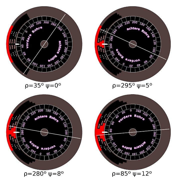
Drawing 31. The maximum salvo deflection indicators for several values of the spread angle and gyro angle
Description of the component for entering the target bearing:
The target bearing ω – used for calculation of the parallax correction and gyro angle – is transmitted to the calculator by means of a selsyn link. The double selsyn receiver received the bearing from one of three (UZO on the bridge, attack periscope in the conning tower, and sky periscope in the control room) target bearing transmitters (Germ. Ziel-Geber) selected by means of the selection switch (Zielrichtung) at the aiming subsystem control box. A double compound indicator with two dials – one in the range 0 to 360° and the other in the range 0 to 10° was integrated with the receiver.
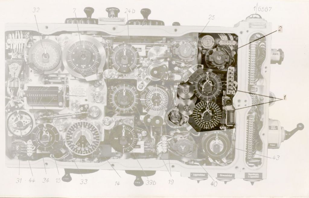
Photo 17. The component for entering the target bearing
(1) target bearing dial
(2) motor of the component for entering the target bearing
Each dial was fitted with two pointers – one of them rotated on the central axis and showed the value received by the selsyn receiver, while the other rotated around the edge of dial and showed the current setting entered in the calculator. The difference in the relative position of these pointers was the error signal, which controlled an electric motor that drove the shaft, passing the received target bearing to the calculator internals (the selsyn receiver itself doesn’t have enough torque to drive the calculator internals).
Drawing 32. The component for entering the target bearing [1]
Between the compound dial and the electric motor was a relay which was controlled by means of a follow-up switch (Blauschalter). If released, the relay interrupted the connection between the dial and the electric motor – the current target bearing from the periscope/UZO did not alter the calculator settings. When the order “Follow-up the target” (Folgen!) was issued, the follow-up switch was triggered and the relay connected the dial with the electric motor, thus the current target bearing was entered into the calculator. This feature made possible updating the target bearing (when the follow-up switch was in the “Folgen!” position), but when it was needed to scan the whole horizon – to not alter the correct calculator settings – the order “do not follow-up target” (Blau! Nicht folgen!) was given and the follow-up switch was released, and the relay disconnected the electric motor from the dial.
In case of damage to the electric motor or the selsyn links transmitting the bearing from the bearing transmitters to the calculator, there was a knob for entering the target bearing manually. This knob was coupled by means of the differential gear with the shaft transmitting the target bearing into the calculator internals. In such a situation the calculator operator manually set the target bearing verbally passed from the torpedo officer (when the selsyn link failed) or matched the pointers positions on the dials (in the case of electric motor failure).
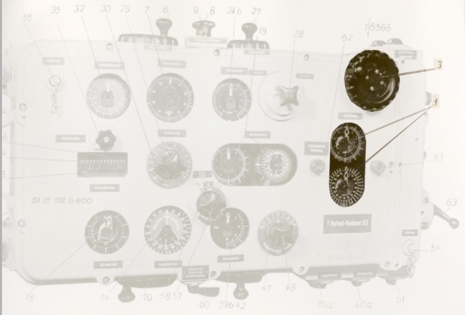
Photo 18. The target bearing dial (1) and the knob (3)
The component for entering the target bearing also took into account the correction for the angular speed of the U-Boat turn. This correction was connected with the torpedo gyro starting-up delay, which was equal to tv = 0.4 sec. During this time, the gyro of the torpedo was locked in one position. That means that when the U-Boat was turning during the torpedo launch, the longitudinal axis of the torpedo (together with the locked gyro) was turned by the angle \(t_{v}*\frac{φ}{t}\), where \(\frac{φ}{t}\) was the angular speed of the turn, which depended on the U-Boat speed and main rudder deflection.
|
speed [knots] |
30° | 15° | |
| ↑ |
17.5 | 2.5 | 1.8 |
| 12 | 1.7 | 1.25 | |
| ↓ | 8 | 1.4 | 1.0 |
| 4.5 | 0.85 | 0.6 |
This correction was taken into account by adding it to the target bearing. It was entered manually by means of the knob. The resulting target bearing was slightly different from the real target bearing, presented on the target bearing dial.
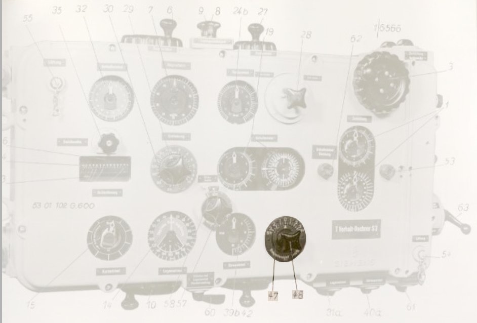
Photo 19. The knob (48) and the indicator (47) for entering the correction for the angular speed of the turn
Description of the component for calculating current angle on the bow:
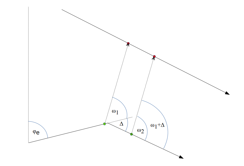
When the target and the U-Boat were cruising on a constant course, the changes of the target bearings were equal to the changes of the angles on the bow.
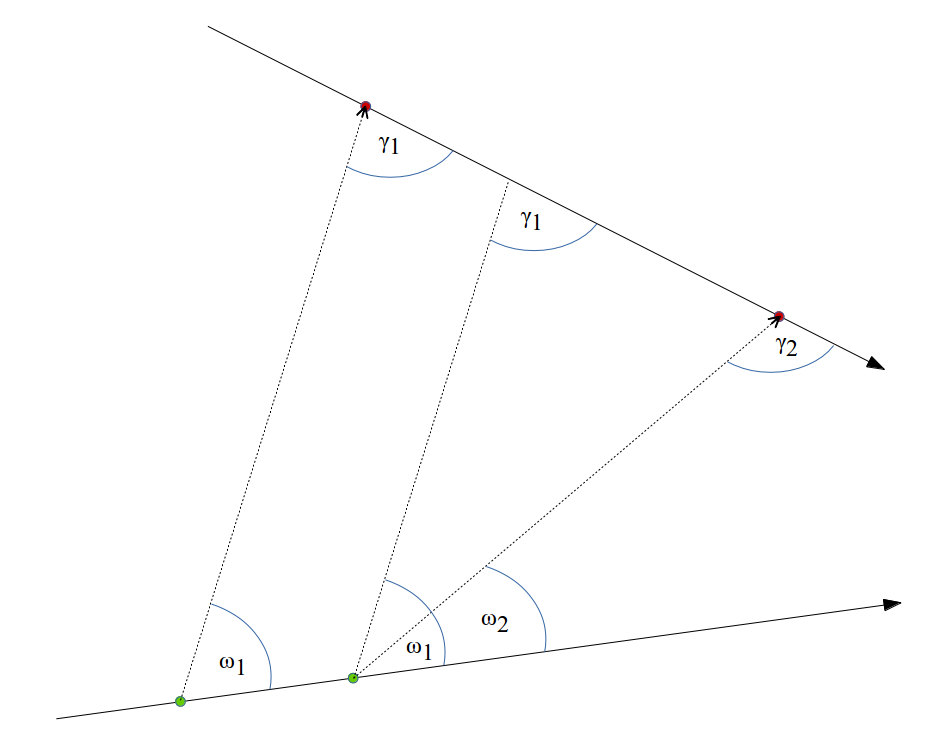
Drawing 33. The change of the target bearing and angle on the bow, while cruising on a constant course
In other words, the difference of the angles on the bow and the difference of the target bearings was equal:
Δ = ω1 – ω2 and Δ = γ1 – γ2
It can be transformed to the following:
ω1 – ω2 = γ1 – γ2
that is:
ω1 – γ1 = ω2 – γ2
So, in any moment (assuming a constant course of the own vessel and the target), the difference of the target bearing and angle on the bow is constant.
This feature was utilized in the component for calculating current angle on the bow, which updated the value of the angle on the bow entered initially.
Drawing 34. The component for calculating current angle on the bow [1]
This component included the selsyn receiver, which received the value of own course φe from the gyro-compass. The value of the course was passed to the one of two inputs of the comparator. The second input of the comparator received the difference between the angle on the bow γ and the target bearing ω. If the target bearing (due to target movement) was changed, the difference between the target bearing and angle on the bow also changed. The change of this difference was compared with the unchanged value of own course and generated the error signal, which controlled the electric motor, which through the differential gear altered the angle on the bow to restore the previous value of the difference between the target bearing and angle on the bow.
Between the own course φe receiver and the comparator was an electro-magnetic coupling, controlled by the switch “Current angle on the bow” (Lage laufend). When the coupling was engaged, the value of own course was passed to the comparator, and the whole component automatically updated the angle on the bow. When the coupling was disengaged, the value of own course was not passed to the comparator. In such a case, the angle on the bow could be updated manually by means of the knob. In such a situation – due to disengaged coupling – the input shaft of the comparator could rotate idle. Because the input shafts inside the comparator were coupled by means of the differential gear, the not-loaded shaft representing the course value was rotated by the same amount as the shaft representing the difference of the angle on the bow and target bearing. Therefore, despite changing the value of the difference of the angle on the bow and target bearing (due to manually changed the angle on the bow), the error signal produced by comparator was zero and the electric motor updating the angle on the bow was disabled. After finishing manual updates of the angle on the bow, the switch “Current angle on the bow” was triggered to engage the coupling, connecting the course receiver with the comparator.
It should be noted that the component for calculating current angle on the bow also compensated for changes to the target bearing resulting from the changes of own course.
If own course φe was changed by value Δ, it meant, that the target bearing was also changed by the same value.
Drawing 35. Change in bearing due to change of own course
That means, that both values (the difference ω – γ and φe) passed to the comparator were changed by the same value – the error signal produced by comparator was zero – the electric motor updating the angle on the bow was disabled – and the angle on the bow was unchanged besides the change of target bearing. The dial with the scale in range from 0 to 10° was integrated with the comparator. This dial showed the relative change of course of the U-Boat.

Photo 20. The component for calculating current angle on the bow
(15) own course change dial, (31) motor of the component for calculating current angle on the bow
It should be noted, that in the torpedo calculator from U 955, the dial has a range up to 60 and is labeled as "Vorlf. sek." that is "time of the initial run (of the torpedo)". This is most likely because during renovation the original dial was replaced with a spare dial without caring that it was not identical to the original. This dial is not related with the time in any way.
Description of the component for calculating the current target bearing:
In the case of salvo launching, the torpedoes were fired in sequence at time intervals equal to 2.3 seconds (later in the war this interval was changed to ~8 seconds to keep the wakes from interfering with the other torpedoes). So, the launching of a four-torpedo salvo (or even a six-torpedo salvo in the case of type XXI U-Boats) took from 9 to 14 seconds. All that time – to keep the gyro angle correct (which among others is the sum of the target bearing) – the periscope/UZO had to be aimed at the target. The torpedo officer had to be focused all that time on aiming and due to tactical reasons this was not desired. That's why the calculator was fitted with the component for calculating the current target bearing.

Drawing 36. The component for calculating the current target bearing [1]
This component consists of a comparator, to which one input is connected by means of the electro-magnetic coupling with the own course receiver. The second input receives the target bearing. The error signal produced by the comparator can be connected – by means of the relay – to the electric motor, driving the shaft responsible for entering the target bearing to the calculator internals.
The electro-magnetic coupling and the relay are engaged at the moment of triggering the firing lever (Abfeuerschalter) – at the moment of launching the first torpedo of the salvo. If the firing subsystem switch (Einzelnschuß) is in the “single shot” position – the control of the coupling and the relay is disabled.
Drawing 37. The control of the component for calculating the current target bearing [1]
At the moment of triggering the firing lever (the launching of the first torpedo), the electro-magnet coupling connected the comparator with the own course receiver and the error signal produced by comparator controls (instead of the error signal from the target bearing dial) and the electric motor driving the shaft, responsible for entering the target bearing to the calculator internals. That means, that since this moment, the bearing pointed to by the periscope/UZO has no influence on the calculator settings. Moreover, the U-Boat can turn during the salvo shot – the change of bearing resulting from the course change is compensated for and the gyro angle will be updated. Because in the circuit there is no latching relay, the firing lever has to be pushed till the last torpedo in the salvo is launched (which is signaled on the torpedo control lamps table).
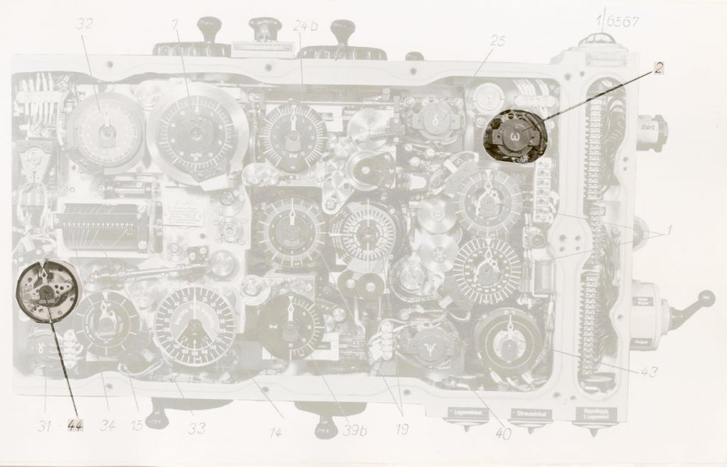
Photo 21. The component for calculating the current target bearing
(2) motor of the component for entering the target bearing
(44) comparator of the component for calculating the current target bearing
References:
[1] Die Torpedos der deutschen U-Boote, Eberhard Rössler