
")
Torpedo directors
With the introduction of the new weapon, the torpedo, it was necessary to create a torpedo fire control system. The main task of such a system is to determine the angle between the current bearing to the moving target and the point where a fired torpedo will intercept the target. In the simplest case we are dealing with a straight running torpedoes launched from fixed and trainable torpedo tubes mounted on the deck of a warship.

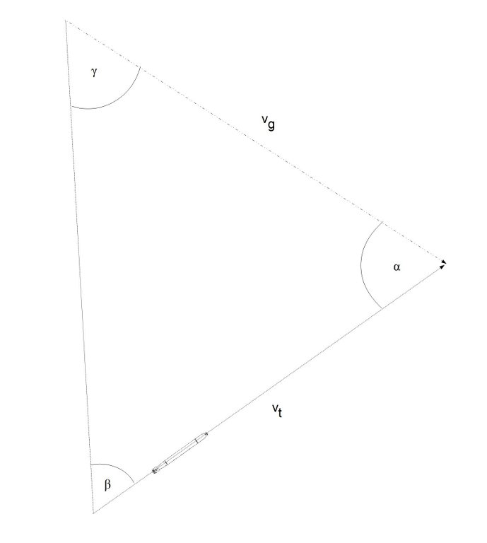
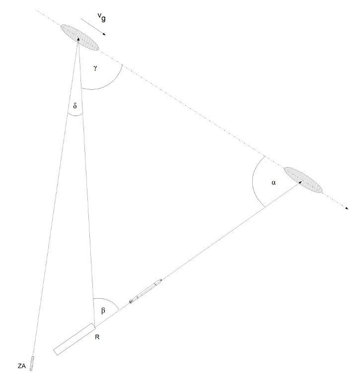
The figure above shows the relative position of the torpedo launcher and target, together with the distances and angles.
γ – angle on bow, Germ. Lage (Lagenwinkel), – angle between target course and target bearing, measured from 0 to 180 degrees right (angle on bow starboard) and left (angle on bow port) beginning from the target bow
α – track angle, Germ. Schneidungswinkel – angle between target course and torpedo course, measured from from the target's bow
β – deflection angle, Germ. Vorhalt (Vorhaltwinkel) – angle between target bearing and torpedo course
E – distance, Germ. Entfernung - distance to the target at the moment of torpedo launch
e – torpedo run, Germ. Schußweite, length of the torpedo run
vt – torpedo speed, Germ. Torpedogeschwindigkeit
vg – target speed, Germ. Gegnerfahrt
Let's assume, that at the moment t0 we launch a torpedo in the direction relative to the current target bearing with angle β. After time t the torpedo hits the target. During this time, the target covered distance vg * t, and the torpedo covered distance e = vt * t. Distances covered by the target and torpedo are directly proportional to the speed of the target and torpedo respectively. So the drawing above can be easily converted to the following:
The law of sines can be applied to this triangle. Knowing the angle on the bow γ, target speed vg and torpedo speed vt the deflection angle β can be calculated:
that is
It should be noted, that to calculate the deflection angle β knowing the distance to the target E is not required.
So the deflection angle could be calculated by performing two arithmetic operations and double checking the table of trigonometric functions – a process which is quite simple, but error-prone – especially during combat.
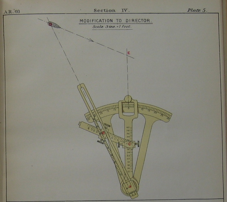
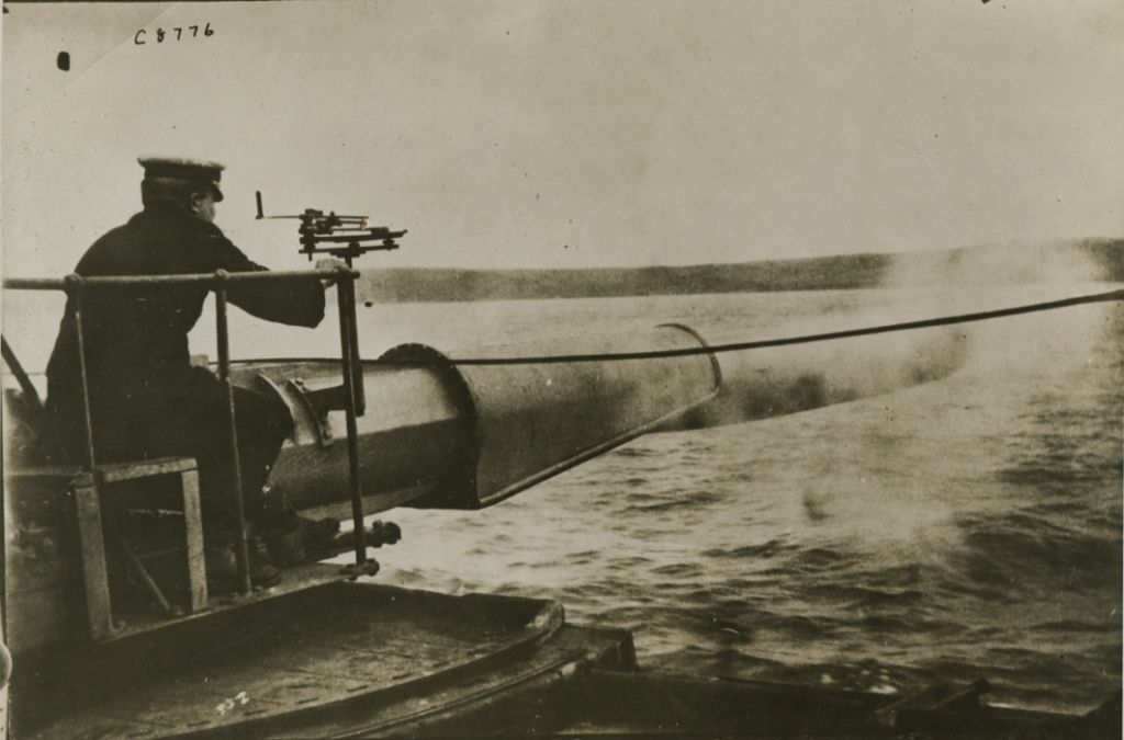
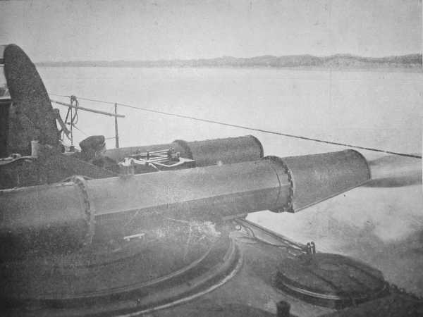
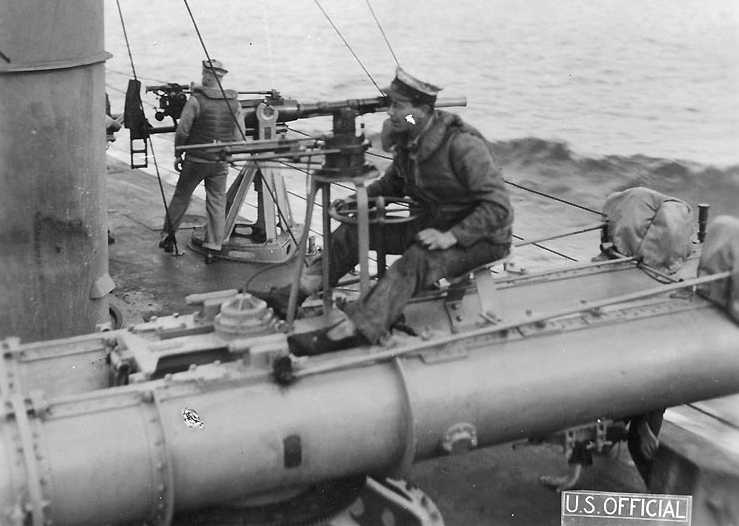
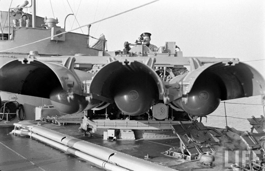
The torpedo triangle problem could be solved with help of a simple torpedo director, which was installed on the torpedo tube (Germ. Zielapparat). This device included the function of the “calculator” and sight.
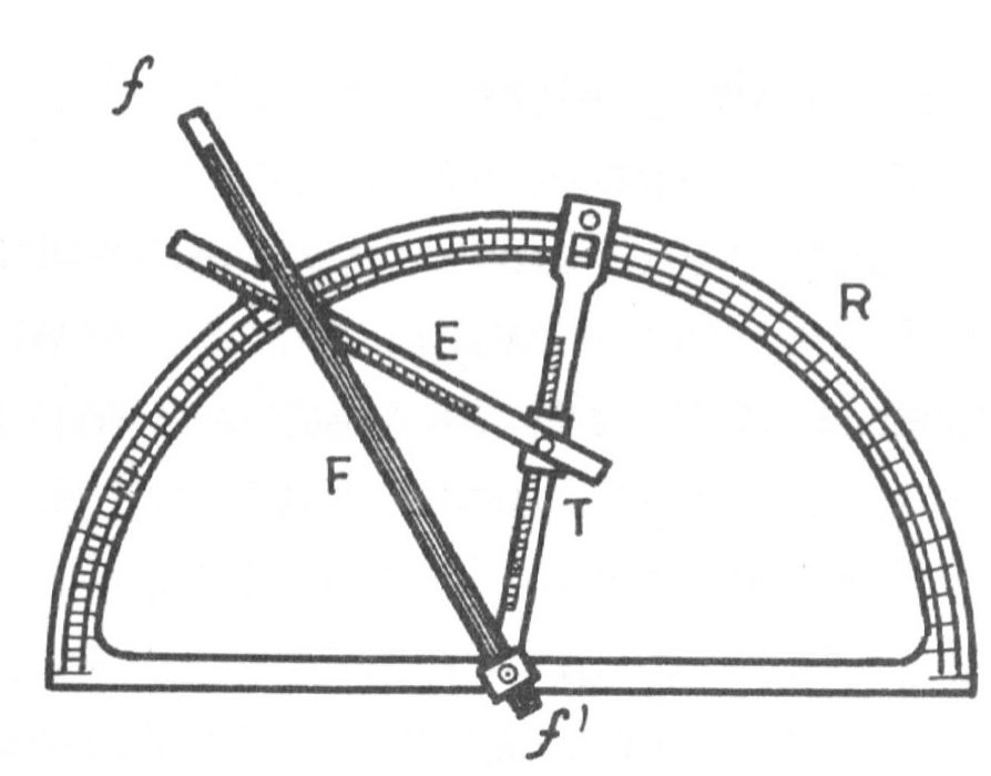
It consisted of three bars - torpedo bar T, sight bar F and target bar E - which were interconnected together in such a way to form the torpedo triangle. The sliding connection of the sight bar and target bar allowed for changing the length of the target bar depending on target speed. By shortening or lengthening the sight bar the estimated angle on the bow could be set. Assuming that the sight bar points toward the target, the torpedo should be fired in the direction of the torpedo bar. In practice, the torpedo bar represents the torpedo tube, and after setting the target speed and the angle on bow, the aiming started - either by training the torpedo tubes (in the case of trainable tubes), or by changing the course of the vessel (in the case of fixed tubes) - so that the target was on the line indicated by the sight bar.
Initially the angle between the sight bar and target bar was set by eye, but soon they began to equip directors with scales for accurate setting of the angle on the bow.

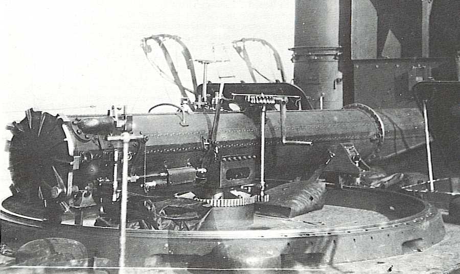
Over time, the torpedo directors - especially on larger vessels such as cruisers and battleships - were located in armored conning towers or combat platforms. These sites were situated much higher than the torpedo tubes, and therefore provided more favorable conditions for observation, greater range, and they were not obscured by smoke from firing guns or splashing waves. The torpedo director operators were a little more protected from enemy fire, which made them more comfortable resulting in their being more precise in the heat of battle. It also allowed a "centralization" of torpedo fire control – the torpedo triangle solution was determined in one central place, and not just on any one launcher - so that the same target data (speed and angle on the bow) could be transferred to many torpedo tube stations instead of just one.
In the case of a vessel armed with fixed torpedo tubes, the vessel had to turn until the target was aligned with the sight, and when that happened the order to launch was given.
In the case of trainable torpedo tubes, they were passed the angle of tube rotation relative to the longitudinal line of the vessel, and then - when the target was aligned with the sight the order to launch was given.
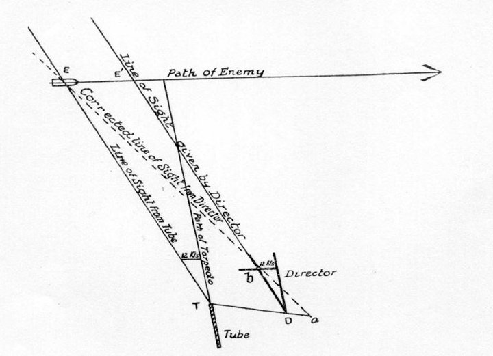
However, when the torpedo director was located in a different place than the torpedo tube, the problem of parallax (Germ. Parallaxenfehler) - angular difference at which the target is seen from the torpedo director station and torpedo tubes had to be taken into consideration.
The magnitude of this angular difference depends on the distance from the target (the larger the distance, the smaller the angular difference), and the bearing to the target (the greater the bearing, the greater the angular difference).
The correction δ resulting from parallax was read from dedicated tables and added to the deflection angle calculated by the torpedo director.
The Royal Navy introduced torpedo directors which were able to take into account the correction for parallax using an extra bar called the “tangent bar”.
This additional bar was located at the junction of the torpedo and sight bars, allowing the operator to move the pivot point of the sight bar by a specific value.
The principle of operation was as follows: suppose that the torpedo director was installed in the conning tower at point D at a distance T from the torpedo tubes. The target was located at E and was cruising at speed v on the course indicated on the drawing. If the director was located on the tube, the line of sight would be the line TE. If the director in the conning tower was set the same as for the torpedo tubes, the line of sight from the battle station would be DBE' and a torpedo fired when the target went through the sight would leave the launcher too late and miss going astern. Therefore, the line of sight of DBE' must be moved so as to pass through the point E.
If we draw a line connecting points E and b, and then extend it till it crosses the line passing through T and D (at point a), the line abE will be the sight line incorporating parallax correction, and the length of the segment Da indicates how much the aft end of the sight bar should be moved.
Because the triangles aTE and ADb are similar, we get:
that is
Db – length of the sight bar
aT – distance between the torpedo director in the conning tower and the torpedo tube
TE – distance to the target at the moment of torpedo launch
Because Db and aT are constant, the value aD can be calculated for any necessary distance to the target. So the additional bar (tangent bar) can be simply scaled in the units respective to the distance to the target.
While using this type of torpedo director it was found that errors during estimation of target speed and angle on the bow are much grater than the error resulting from parallax, so this director modification was abandoned. Additionally, there also were errors in operating this director (i.e. setting the tangent bar in the opposite direction).

Another correction included while aiming above-water torpedo tubes was order-delay (Germ. Befehlsverzug). Order-delay means the time that elapsed between giving the launch order and the torpedo entering the water. Order-delay consisted of the delay in passing the order, operation time of the torpedo tube launching gear, the time it took the torpedo to leave the tube and the time of flight of the torpedo through the air. The order-delay was especially important when launching torpedoes from the broadside torpedo tubes. Order-delay was determined experimentally and written down in special tables. This delay in connection with the forward movement of the launching vessel caused shifting of the real torpedo track relative to the track determined by the torpedo director. For example, when order-delay was 1 second and own ship speed was 20 knots, the torpedo entered the water at a distance of 10 meters from the line determined by the torpedo director.
Another correction was angular-speed of turn of a ship turning while launching a torpedo (Germ. Winkelgeschwindigkeit). It was connected with delay in starting-up the torpedo gyro. While the gyro wheel was accelerated, it was locked to prevent its main axis changing position relative to the longitudinal axis of torpedo. This took from 0.5 to 0.7 seconds. If the launching ship performed a turn with an angular speed ω, for the time t, the longitudinal axis of the torpedo (together with starting the gyro) rotated with angle ω * t relative to the track determined by torpedo director. The greater the distance to the target, the greater shifting of the intersection of the torpedo track with target course would be. For example, when gyro spinning-up time is 0.5 seconds and the angular speed of turn is 1º/s, and distance to target is 1000 meters, the intersection was shifted 17 meters, but when the distance is 3000 meters, the intersection shifted 52 meters.
This correction was determined from dedicated tables and added to the deflection angle calculated by torpedo director.
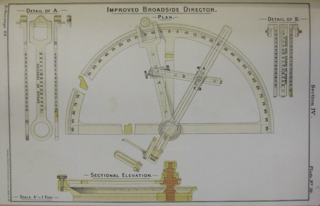
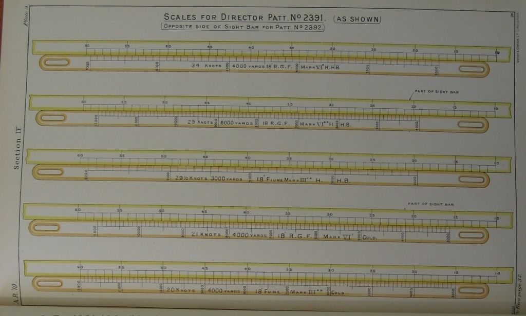
During a torpedo attack the important issue was to determine if the target is in range of the torpedo. The answer to this question was possible after a simple modification of the torpedo director. A special bar, called “Possible Shot Scale” (Germ. Reichwietenlineal), was added which was parallel to the sight bar.
Initially, the scale was applied directly to the sight bar, in the same units as the scales of torpedo and target speed.
From the drawing we get following relationship:
\[\begin{aligned} \frac{AD}{AE} = \frac{AB}{AC} \end{aligned} \]
AD – distance to target at the moment of torpedo launch
AE – torpedo range
AB – the value read from the scale on the sight bar
AC – speed of the torpedo
For the sample data (torpedo speed: 30, value read from the scale on the sight bar: 40, maximum range of the torpedo: 2000) we get:
AD = AB / AC * AE = 40 / 30 * 2000 = 2666 meters
That means that a torpedo with a maximum range of 2000 meters reaches the target, if it – at the moment of torpedo launch – is at a distance not greater than 2666 meters.
If the torpedo maximum range and torpedo speed are constant, then the value AC * AE also will be constant – that means, that distance to the target at the moment of launch will be in direct proportion to the value read from the scale on the sight bar. So this scale can be applied in the correct units, rescaled by the component AC * AE. Thus the maximum target distance at the moment of launch can be read directly from the scale, avoiding calculations.

In practice, the range scale was applied with a separate bar which could be installed on the sight bar. Thus with one torpedo director, many types of torpedoes (which differed in maximum range and speed) could be used by simply replacing the range bar.
Small modifications were often made to torpedo directors to improve their functionality. They were equipped with sighting telescopes, additional angular scale plates which allowed direct reading of track angle and luminescent sight graticules.


Demonstration showing the operation of the torpedo director is available here.
References:
[1] Britain Torpedoes Pre-World War II
[2] Antoni Komorowski, Broń torpedowa
[3] Torpedo Director Pattern 1192
[4] Handbook of Torpedo Control, 1916, ADM 186/381
[5] Royal Navy Torpedo Director - 1909
[6] Torpedo Director Pattern 1193
[7] Torpedo Director Pattern 2391
[8] Possible Shot Scale
[9] Torpedo Director
[10] The 1st Class Torpedo Boat The Countess of Hopetoun
[11] United States of America Torpedoes Pre-World War II